CAD Model Download
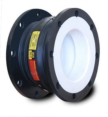
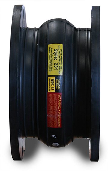
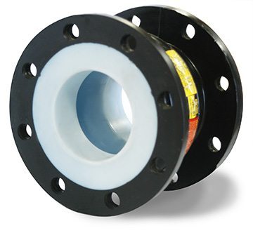
Proco Series 231/ET
The Proco Series 231/ET Lined Expansion Joints are designed for tough, demanding, corrosive chemical applications such as chemical and petrochemical process facilities and highly corrosive industrial piping and pollution control systems. Use of the 231/ET expansion joints is especially prevalent in the paper industry, where their ability to resist corrosive attack at elevated temperature and pressure is unrivaled by other competitive metal or plastic expansion joints.
Series 231/ET expansion joints are chemically resistant against the entire pH range, and can easily handle tough pulp/paper applications including:
- White-green-black liquor
- Beach plant chlorination
- Caustic extraction stages
The new 231/ET has been completely re-engineered to provide even more strength, flexibility and movement capabilities. Manufactured using tire cord industry technology, the Series 231/ET combines woven polyester tie cord into a fabric matrix, which is then bonded with a EPDM elastomer that is reinforced with metal and bonded to a PTFE liner. This combination creates a product with an increased operating performance.
Some notable features of the PROCO Series 231/ET include:
- Greater movements with a lower/wider arch profile
- Chemical service capability at minimal cost
- Absorption of pipe movements and stress
- Reduction of system noise
- Isolation of mechanical vibrations
- Compensation for alignment/offset
- Elimination of electrolytic action and electrolysis
- Protection against start up and surge forces
For more information about the features and benefits of the PROCO Series 231/ET, download our brochure.
For up-to-date pricing and availability information, contact PROCO today.
|
EXPANSION JOINT SIZE |
NEUTRAL LENGTH |
231/ET Movement Capability: From Neutral Position | Operating Conditions 5 |
Weights in lbs / (kgs) 6 | Flange Dimensions and Drilling 8 | |||||||||||||
|
Axial Compression |
Axial Extension |
Lateral Deflection |
Angular Deflection2 |
Torsional Rotation3 |
Thrust Factor4 |
Positive |
Vacuum Inches of Hg / (mm of Hg) | Joint Assembly | Retaining Ring Set | Control Unit 7 Assembly | O.D. of Exp. Joint / Ring Inch / (mm) |
Bolt Circle |
Number of Holes |
Size of Holes |
||||
| 1.5 | (40) | 6 | (150) |
1.25 |
0.625 |
0.625 |
28.0˚ | 1˚ |
1.8 |
225 |
30 |
1.5 |
2.5 |
2.3 |
5.0 |
3.88 |
4 |
0.625 |
| 2 | (50) | 25.0˚ |
3.1 |
225 |
30 |
2.0 |
4.0 |
2.8 |
6.0 |
4.75 |
4 |
0.750 |
||||||
| 2.5 | (65) | 20.2˚ |
4.9 |
225 |
30 |
2.5 |
4.5 |
2.8 |
7.0 |
5.50 |
4 |
0.750 |
||||||
| 3 | (80) | 18.0˚ |
7.1 |
225 |
30 |
3.0 |
5.5 |
2.8 |
7.5 |
6.00 |
4 |
0.750 |
||||||
| 4 | (100) | 14.2˚ |
12.5 |
225 |
30 |
4.0 |
8.0 |
2.8 |
9.0 |
7.50 |
8 |
0.750 |
||||||
| 5 | (125) | 13.0˚ |
19.6 |
225 |
30 |
5.0 |
8.5 |
4.0 |
10.0 |
8.50 |
8 |
0.875 |
||||||
| 6 | (150) | 12.2˚ |
28.3 |
225 |
30 |
7.0 |
9.5 |
4.0 |
11.0 |
9.50 |
8 |
0.875 |
||||||
| 8 | (200) | 12.0˚ |
50.3 |
210 |
30 |
11.0 |
14.5 |
8.0 |
13.5 |
11.75 |
8 |
0.875 |
||||||
| 10 | (250) | 10 | (200) |
2.0 |
1.0 |
1.0 |
11.9˚ |
78.5 |
210 |
30 |
19.0 |
17.0 |
10.0 |
16.0 |
14.25 |
12 |
1.000 |
|
| 12 | (300) | 11.3˚ |
113.1 |
210 |
30 |
29.0 |
24.5 |
10.0 |
19.0 |
17.00 |
12 |
1.000 |
||||||
| 14 | (350) | 11.5˚ |
153.9 |
150 |
30 |
38.0 |
27.0 |
12.0 |
21.0 |
18.75 |
12 |
1.125 |
||||||
| 16 | (400) | 10.1˚ |
201.1 |
150 |
30 |
44.0 |
33.5 |
15.0 |
23.5 |
21.25 |
16 |
1.125 |
||||||
| 18 | (450) | 8.9˚ |
254.5 |
150 |
30 |
49.0 |
34.0 |
16.5 |
25.0 |
22.75 |
16 |
1.250 |
||||||
| 20 | (500) | 8.1˚ |
314.2 |
150 |
30 |
54.0 |
38.0 |
16.5 |
27.5 |
25.00 |
20 |
1.250 |
||||||
| 24 | (600) | 10 | (250) |
3.0 |
1.5 |
1.5 |
9.0˚ |
452.4 |
110 |
28 |
60.0 |
48.0 |
20.0 |
32.0 |
29.50 |
20 |
1.375 |
|
| 30 | (750) | 7.5˚ |
706.9 |
100 |
28 |
88.0 |
63.0 |
29.5 |
38.8 |
36.00 |
28 |
1.375 |
||||||
| 36 | (900) | 6.7˚ |
1017.9 |
100 |
28 |
112.0 |
76.0 |
43.0 |
46.0 |
42.75 |
32 |
1.625 |
||||||
Notes:
1. PTFE liner extends to bottom of bolt holes.
2. The degree of angular movement is based on the maximum rated extension.
3. Torsional movement is expressed when the expansion joint is a neutral length.
4. To determine “end thrust”, multiply thrust factor by operating pressure of system.
5. Pressure rating is based on 194°F operating temperature. At higher temperature the pressure rating is slightly reduced.
6. Weights are approximate.
7. Control unit weight consists of one rod, four washers, three nuts and two control rod plates. Multiply number of control units needed for
application (as specified in the Fluid Sealing Association Technical Handbook) to determine correct weights.
8. Dimensions shown are in accordance with 125/150# standards of ANSI B-16.1, B-16.24, B-16.5; AWWA C-207 Table 1 and 2 Class D.