Proco Series 300
Each Proco Series 300 Flanged Rubber Pipe Connector is specifically engineered for your particular application. Multiple plies of tough fabric and helical spring steel wire are embedded into the pipe wall during the manufacturing process, resulting in a product precisely designed for your pressure and vacuum requirements.
Available styles include:
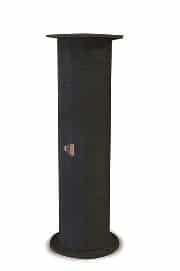
Style 310-R
The Style 310 is precision molded to specific lengths, as listed in Table 3. The built-in rubber flanges are manufactured to adhere to ANSI 125/150# drilling specifications.
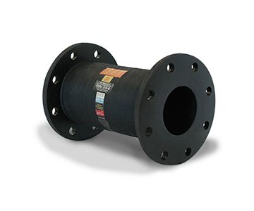
Style 310
The Proco Style 310 is manufactured using conventional methods which allow for fabrication to a specific custom length requirement. It is also available in pre-manufactured lengths (shown in Table 3). The Style 310 is standard with 125/150# drilling, but can also be fabricated to meet other drilling patterns.
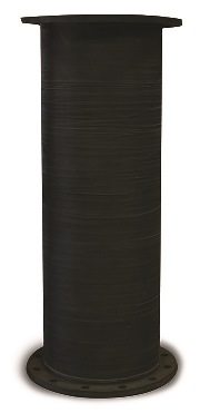
Style 320
The Style 320 is designed for high-pressure applications and is manufactured similarly to Style 310. Flanges are usually produced to ANSI 250/300# drilling specifications, but other drilling patterns can be accommodated upon request.
Some notable features of the Series 300 Flanged Rubber Pipe Connectors include:
- Electrolysis and electrolytic action prevention
- Compensation for systems misalignment
- Chemical or abrasive service capability at minimal cost
For more information about the features and benefits of the Proco Series 300, download our brochure:
For up-to-date pricing and availability information, contact PROCO today.

| Table 1: Comparison of Material Acoustical Impedances | ||||
| Material |
Sound Velocity |
Density |
Acoustical Impedance |
Relative Impedance |
|
Steel |
206,500 |
.283 |
58,440 |
551.3 |
|
Concrete |
198,000 |
.072 |
14,260 |
134.5 |
NOTES:
Acoustical impedance is defined as the product of material density times velocity of sound in that material. In acoustical systems low impedance corresponds to low sound transmission.
Relative impedance is based on Rubber = 1.0
| Table 2: Available Styles and Materials | |||||||
| 310 | 310-R | 320 | PROCO Material Code | Cover Elastomer | Tube Elastomer | Maximum Operating Temp ˚F | F.S.A. Material Class |
|
• |
• |
• |
BB |
Chlorobutyl |
Chlorobutyl |
250˚ |
Special II |
|
• |
• |
BT |
Chlorobutyl |
Teflon® |
250˚ |
Special II |
|
|
• |
• |
EE |
EPDM |
EPDM |
250˚ |
Special II |
|
|
• |
• |
NR |
Neoprene |
Natural |
180˚ |
Std. I |
|
|
• |
• |
• |
NH |
Neoprene |
CSM |
212˚ |
Std. II |
|
• |
• |
• |
NN |
Neoprene |
Neoprene |
225˚ |
Std. II |
|
• |
• |
• |
NP |
Neoprene | Nitrile | 212˚ | Std. II |
Product “cover” can be CSM coated on special order.
Style 310/NN meets ASTM, Class A. Type III and conforms to all USCG requirements.
NOTES:
1. Teflon is a registered trademark of the DuDont Company.
2. Products with Teflon® “tubes” are not recommended with vacuum service.
Reduce System Stress And Strain.
Rigid attachment of piping to critical or mechanical equipment can produce excessive loading. Thermal or mechanically created strain-stress-shock are cushioned and absorbed with the installation of a flexible PROCO Series 300 Rubber Pipe.
Full Flow With Less Turbulence Or Material Entrapment.
The smooth bore of the PROCO Series 300 Rubber Pipe Connector allows full flow without turbulence. Metallic connectors depend upon bellows or convolutions to absorb motion. These bellows/ convolutions could create flow turbulence and also create an area for material entrapment or bacteria growth.
Leak Free Without Gaskets Or Packing.
The full-face rubber flange of the PROCO Series 300 Rubber Pipe Connector is self gasketing.
Additionally, the Style 310-R features a molded in place “O-Ring” on each flange-face for faster sealing with less torque at installation and less long-term maintenance. Unlike interlocked metallic connectors, the Series 300 features a onepiece seamless tube that does not require packing. Our rubber connector is suitable for all air, gas, and fluids, including “searching” thin fluids.
Control Rod Assembly Usage.
PROCO Style 491 Control Units are designed to protect the Series 300 Pipe Connector from excessive elongation. Control rods must be used: (1) when the piping containing the rubber pipe connector is not anchored and, (2) when the rubber pipe connector is attached to resiliently supported pipe or equipment.
| Nominal Pipe Size: Pipe I.D. | Neutral Length | Movement Capability From Neutral |
125/150# |
Rubber Pipe Dimensions | Approx. Weight (lbs) | Operating Pressures 3 | ||||||||||
| In. of Axial Compression | In. of Axial Extension | ± In. of Lateral Deflection | ± In. of Angular Deflection | Flange O.D. | Bolt Circle | # of Holes | Size of Holes | “A” Flange Thickness | “B” Body Thickness | Style 310-R | Retaining Rings (Set) | Style 310-R | Style 310 | Style 320 | ||
| .75 |
12* |
.158 |
.158 |
1.97 |
21.8˚ |
3.875 | 2.750 | 4 | 0.625 | 0.591 | 0.472 |
2.4 |
1.5 |
300 |
150
|
300 |
| 1 |
12* |
.158 |
.158 |
1.77 |
17.7˚ |
4.250 | 3.120 | 4 | 0.625 | 0.591 | 0.551 |
3.3 |
1.9 |
|||
| 1.25 |
12* |
.158 |
.158 |
1.58 |
14.0˚ |
4.625 | 3.500 | 4 | 0.625 | 0.591 | 0.551 |
4.0 |
2.4 |
|||
| 1.5 |
12* |
.158 |
.158 |
1.39 |
11.3˚ |
5.000 | 3.880 | 4 | 0.625 | 0.591 | 0.551 |
4.3 |
2.6 |
|||
| 2 |
12* |
.158 |
.158 |
1.18 |
9.1˚ |
6.000 | 4.750 | 4 | 0.750 | 0.591 |
0.551
|
5.6 |
2.6 |
250 |
250 |
|
| 2.5 |
12* |
.158 |
.158 |
.98 |
7.0˚ |
7.000 | 5.500 | 4 | 0.750 | 0.591 | 0.551 |
6.9 |
5.3 |
200 | ||
| 3 |
12* |
.158 |
.158 |
.79 |
5.7 |
7.500 | 6.000 | 4 | 0.750 | 0.591 | 0.551 |
8.6 |
5.6 |
175
|
||
| 3.5 |
12 |
.158 |
.158 |
.59 |
5.1˚ |
8.500 | 7.000 | 8 | 0.750 | 0.591 | 0.669 |
9.7 |
6.5 |
|||
| 4 |
12 |
.158 |
.158 |
.59 |
4.6 |
9.000 | 7.500 | 8 | 0.750 | 0.591 | 0.669 |
10.9 |
7.3 |
|||
| 5 |
12 |
.158 |
.158 |
.45 |
3.7˚ |
10.000 | 8.500 | 8 | 0.875 | 0.591 | 0.669 |
13.5 |
7.9 |
|||
| 6 |
12 |
.158 |
.158 |
.45 |
3.1˚ |
11.000 | 9.500 | 8 | 0.875 | 0.591 | 0.709 |
18.9 |
9.1 |
150
|
||
| 8 |
12 |
.118 |
.118 |
.35 |
1.7˚ |
13.500 | 11.750 | 8 | 0.875 | 0.591 | 0.787 |
23.4 |
14.0 |
|||
| 10 |
12 |
.118 |
.118 |
.32 |
1.4˚ |
16.000 | 14.250 | 12 | 1.000 | 0.787 | 0.866 |
26.0 |
17.0 |
|||
| 12 |
12 |
.118 |
.118 |
.24 |
1.1˚ |
19.000 | 17.000 | 12 | 1.000 | 0.787 | 0.984 |
36.0 |
24.1 |
|||
| 14 |
12 |
.118 |
.118 |
.24 |
1.0˚ |
21.000 | 18.750 | 12 | 1.125 | 0.787 | 0.984 |
58.0 |
26.8 |
125* | 125 | 200 |
| 16 |
12 |
.118 |
.118 |
.24 |
0.7 |
23.500 | 21.250 | 16 | 1.125 | 0.787 | 0.984 |
83.0 |
32.1 |
100* | 100 | 150 |
| 18 |
12 |
.112 |
.112 |
.18 |
0.9˚ |
25.000 | 22.750 | 16 | 1.250 | 0.875 | 1.000 |
110.0 |
34.6 |
|||
| 20 |
24* |
.236 |
.236 |
.24 |
1.4˚ |
27.500 | 25.000 | 20 | 1.250 | 1.000 | 1.000 |
270.0 |
35.9 |
|||
NOTES:
*1. For optimum noise and vibration absorption, use this or longer length
2. The degree of angular movement is based on the maximum rated extension.
3. Pressure rating is based on 170˚F. operating temperature. Vacuum rating is 26” Hg in all cases except where * appears.
Larger I.D. or length sizes are available upon special request. Contact PROCO