CAD Model Download
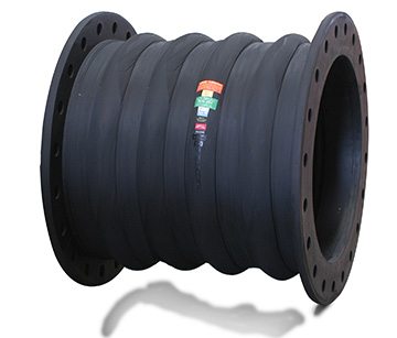
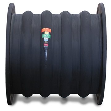
Proco Style 234-L
Proco Style 234-L rubber expansion joints are built to withstand even the most rigorous piping system configurations. They are low-profile, quadruple-wide arch products that are precisely designed to absorb directional movements of rigid pipe systems, as well as reduce noise and vibration, and compensate for misalignment due to long-term settling.
Some of the notable features and benefits of the Proco Style 234-L are:
- Absorption of Directional Movement
- Absorption of Vibration, Noise and Shock
- Compensation for Misalignment
- Wide Range of Service and Lighter Weight
- Easy Material Identification
For more information about the features and benefits of the Proco Series 234-L, download our brochure.
For up-to-date pricing and availability information, contact PROCO today.
Available Styles & Materials
| Cover 1 Elastomer | Tube Elastomer | Maximum Operating Temp. °F (°C) | Branding Label Color | F.S.A. Material Class |
|---|---|---|---|---|
| Chlorobutyl | Chlorobutyl | 250 °F (121°C) | Black | STD. III |
| EPDM | EPDM | 250 °F (121°C) | Red | STD. III |
| EPDM | FDA-EPDM | 250 °F (121°C) | Red² | STD. II |
| Neoprene | CSM | 212 °F (100°C) | Green | STD. II |
| Neoprene | Neoprene | 225 °F (107°C) | Blue | STD. II |
| Neoprene | FDA-Neoprene | 225 °F (107°C) | Blue² | STD. II |
| Neoprene | Nitrile | 212 °F (100°C) | Yellow | STD. II |
| Neoprene | Natural Rubber | 180 °F (82°C) | White | STD. I |
Notes:
All Products are reinforced with Polyester Tire Cord
1. Expansion Joint “Cover” can be coated with CSM UV Resistant Coating.
2. Branding Label will be marked as “Food Grade”.
3. All elastomers above are not intended for steam service.
| Expansion Joint Size Nom. I.D. Inch/(mm) | Neutral Length Inch/(mm) | 234-L Movement Capability:¹ From Neutral Position (Non-Concurrent) | Operating Conditions² | Weights lbs/(kgs)³ | |||||||
| Axial Compression Inch/(mm) | Axial Extension Inch/(mm) | Lateral Deflection Inch/(mm) | Angular Deflection (Degrees) | Torsional Rotation (Degrees) | Thrust Factor In2(cm2) | Positive PSIG (Bar) | Vacuum Inches of Hg/(mm of Hg) | Expansion Joint | Retaining Ring Set | ||
| 2 (50) |
18 (450) |
2.75 (70) |
1.97 (50) |
8 (200) |
63.1° | 2° | 10.03 (64) |
145 |
26 |
6.0 |
4.0 |
| 2.5 (65) |
18 (450) |
2.75 (70) |
1.97 (50) |
8 (200) |
57.6° | 2° | 13.04 (84) |
145 |
26 |
7.0 |
4.5 |
| 3 (80) |
18 (450) |
2.75 (70) |
1.97 (50) |
8 (200) |
52.7° | 2° | 16.44 (106) |
145 |
26 |
11.0 |
5.5 |
| 4 (100) |
18 (450) |
2.75 (70) |
1.97 (50) |
8 (200) |
44.5° | 2° | 24.41 (157) |
145 |
26 |
15.0 |
8.0 |
| 5 (125) |
18 (450) |
2.75 (70) |
1.97 (50) |
8 (200) |
38.2° | 2° | 33.95 (219) |
145 |
26 |
18.0 |
8.5 |
| 6 (150) |
24 (600) |
2.75 (70) |
1.97 (50) |
8 (200) |
33.3° | 2° | 45.06 (290) |
145 |
26 |
31.0 |
9.5 |
| 8 (200) |
24 (600) |
2.75 (70) |
1.97 (50) |
8 (200) |
26.2° | 2° | 72.00 (469) |
145 |
26 |
41.0 |
14.5 |
| 10 (250) |
24 (600) |
2.75 (70) |
1.97 (50) |
8 (200) |
21.5° | 2° | 105.22 (678) |
145 |
26 |
50.0 |
17.0 |
| 12 (300) |
26 (650) |
2.75 (70) |
1.97 (50) |
8 (200) |
18.2° | 2° | 153.25 (988) |
145 |
26 |
66.0 |
24.5 |
| 14 (350) |
26 (650) |
3.15 (80) |
2.36 (60) |
8 (200) |
18.6° | 2° | 200.27 (1292) |
145 |
26 |
82.0 |
27.0 |
| 16 (400) |
26 (650) |
3.15 (80) |
2.36 (60) |
8 (200) |
16.5° | 2° | 253.58 (1636) |
145 |
26 |
97.0 |
33.5 |
| 18 (450) |
26 (650) |
3.15 (80) |
2.36 (60) |
8 (200) |
14.7° | 2° | 313.17 (2020) |
145 |
26 |
107.0 |
34.0 |
| 20 (500) |
26 (650) |
3.15 (80) |
2.36 (60) |
8 (200) |
13.3° | 2° | 379.05 (2445) |
145 |
26 |
141.0 |
38.0 |
| 24 (600) |
26 (650) |
3.15 (80) |
2.36 (60) |
8 (200) |
11.1° | 2° | 562.25 (3627) |
109 |
26 |
180.0 |
48.0 |
| 28 (700) |
30 (750) |
3.15 (80) |
2.36 (60) |
8 (200) |
9.6° | 2° | 742.93 (4793) |
109 |
26 |
260.0 |
55.0 |
| 30 (750) |
30 (750) |
3.15 (80) |
2.36 (60) |
8 200) |
8.9° | 2° | 842.69 (5436) |
73 |
26 |
278.0 |
63.0 |
| 36 (900) |
30 (750) |
3.15 (80) |
2.36 (60) |
8 (200) |
7.5° | 2° | 1179.68 (7610) |
73 |
26 |
341.0 |
76.0 |
| 42 (1050) |
32 (800) |
3.15 (80) |
2.36 (60) |
8 (200) |
6.4° | 2° | 1573.22 (10149) |
73 |
26 |
468.0 |
100.0 |
| 48 (1200) |
32 (800) |
3.15 (80) |
2.36 (60) |
8 (200) |
5.6° | 2° | 2023.31 (13053) |
73 |
26 |
567.0 |
132.0 |
| 54 (1350) |
32 (800) |
3.15 (80) |
2.36 (60) |
8 (200) |
5.0° | 2° | 2460.24 (15872) |
73 |
26 |
646.0 |
150.0 |
| 60 (1500) |
32 (800) |
3.15 (80) |
2.36 (60) |
8 (200) |
4.5° | 2° | 3016.00 (19458) |
73 |
26 |
834.0 |
200.0 |
NOTES:
1. Concurrent Movements – Concurrent movements are developed when two or more movements in a pipe system occur at the same time. If multiple movements exceed single arch design there may be a need for additional arches.
To perform calculation for concurrent movement when a pipe system design has more than one movement, please use the following formula:

Calculation must be equal to or less than 1 for expansion joint to operate within concurrent movement capability.
2. Pressure rating is based on 170˚ F operating temperature with a 4:1 safety factor. At higher temperatures, the pressure rating is reduced slightly. Hydrostatic testing at 1.5 times rated maximum catalog pressure or design working pressure of pipe system for 10 minutes is available upon request.
3. Weights are approximate.
4. The degree of angular movement is based on the maximum rated extension.
5. Torsional movement is expressed when the expansion joint is at neutral length.
6. Calculation of Thrust (Thrust Factor). When expansion joints are installed in the pipeline, the static portion of the thrust is calculated as a product of the area of the I.D. of the arch of the expansion joint times the maximum pressure (design, test or surge) that will occur in the line. The result is a force expressed in pounds.
Take Design, surge or test pressure X thrust factor to calculate end thrust.
7. Parts listed at 26” Hg / 660 mm Hg vacuum have a design rating of 30” Hg / 762 mm Hg (full vacuum). Vacuum rating is based on neutral installed length, without external load. Products should not be installed “extended” on vacuum applications.
| Expansion Joint Size Nom. I.D. Inch/(mm) | Neutral Length Inch/(mm) | FA234-L Movement Capability:¹ From Neutral Position (Non-Concurrent) | Operating Conditions² | Weights lbs/(kgs)³ | |||||||
| Axial Compression Inch/(mm) | Axial Extension Inch/(mm) | Lateral Deflection Inch/(mm) | Angular Deflection (Degrees) | Torsional Rotation (Degrees) | Thrust Factor In2(cm2) | Positive PSIG (Bar) | Vacuum Inches of Hg/(mm of Hg) | Expansion Joint | Retaining Ring Set | ||
|
2 |
18 |
1.38 |
1.0 |
4 |
31.5° | 1° |
3.14 |
145 |
26 |
8.0 |
4.0 |
|
2.5 |
18 |
1.38 |
1.0 |
4 |
28.8° | 1° |
4.91 |
145 |
26 |
10.0 |
4.5 |
|
3 |
18 |
1.38 |
1.0 |
4 |
26.3° | 1° |
7.07 |
145 |
26 |
14.0 |
5.5 |
|
4 |
18 |
1.38 |
1.0 |
4 |
22.2° | 1° |
12.57 |
145 |
26 |
18.0 |
8.0 |
|
5 |
18 |
1.38 |
1.0 |
4 |
19.1° | 1° |
19.64 |
145 |
26 |
22.0 |
8.5 |
|
6 |
24 |
1.38 |
1.0 |
4 |
16.6° | 1° |
28.27 |
145 |
26 |
39.0 |
9.5 |
|
8 |
24 |
1.38 |
1.0 |
4 |
13.1° | 1° |
50.27 |
145 |
26 |
51.0 |
14.5 |
|
10 |
24 |
1.38 |
1.0 |
4 |
10.7° | 1° |
78.54 |
145 |
26 |
62.0 |
17.0 |
|
12 |
26 |
1.38 |
1.0 |
4 |
9.1° | 1° |
113.10 |
145 |
26 |
83.0 |
24.5 |
|
14 |
26 |
1.57 |
1.18 |
4 |
9.3° | 1° |
153.94 |
145 |
26 |
103.0 |
27.0 |
|
16 |
26 |
1.57 |
1.18 |
4 |
8.2° | 1° |
201.06 |
145 |
26 |
121.0 |
33.5 |
|
18 |
26 |
1.57 |
1.18 |
4 |
7.3° | 1° |
254.47 |
145 |
26 |
134.0 |
34.0 |
|
20 |
26 |
1.57 |
1.18 |
4 |
6.6° | 1° |
314.16 |
145 |
26 |
176.0 |
38.0 |
|
24 |
26 |
1.57 |
1.18 |
4 |
5.5° | 1° |
452.39 |
109 |
26 |
224.0 |
48.0 |
|
28 |
30 |
1.57 |
1.18 |
4 |
4.8° | 1° |
615.75 |
109 |
26 |
325.0 |
55.0 |
|
30 |
30 |
1.57 |
1.18 |
4 |
4.4° | 1° |
706.86 |
73 |
26 |
348.0 |
63.0 |
|
36 |
30 |
1.57 |
1.18 |
4 |
3.7° | 1° |
1017.88 |
73 |
26 |
426.0 |
76.0 |
|
42 |
32 |
1.57 |
1.18 |
4 |
3.2° | 1° |
1385.44 |
73 |
26 |
585.0 |
100.0 |
|
48 |
32 |
1.57 |
1.18 |
4 |
2.8° | 1° |
1809.56 |
73 |
26 |
709.0 |
132.0 |
|
54 |
32 |
1.57 |
1.18 |
4 |
2.5° | 1° |
2290.22 |
73 |
26 |
807.0 |
150.0 |
|
60 |
32 |
1.57 |
1.18 |
4 |
2.2° | 1° |
2827.43 |
73 |
26 |
1043.0 |
200.0 |
NOTES:
1. Concurrent Movements – Concurrent movements are developed when two or more movements in a pipe system occur at the same time. If multiple movements exceed single arch design there may be a need for additional arches.
To perform calculation for concurrent movement when a pipe system design has more than one movement, please use the following formula:
Calculation must be equal to or less than 1 for expansion joint to operate within concurrent movement capability.
2. Pressure rating is based on 170˚ F operating temperature with a 4:1 safety factor. At higher temperatures, the pressure rating is reduced slightly. Hydrostatic testing at 1.5 times rated maximum catalog pressure or design working pressure of pipe system for 10 minutes is available upon request.
3. Weights are approximate.
4. The degree of angular movement is based on the maximum rated extension.
5. Torsional movement is expressed when the expansion joint is at neutral length.
6. Calculation of Thrust (Thrust Factor). When expansion joints are installed in the pipeline, the static portion of the thrust is calculated as a product of the area of the I.D. of the arch of the expansion joint times the maximum pressure (design, test or surge) that will occur in the line. The result is a force expressed in pounds.
Take Design, surge or test pressure X thrust factor to calculate end thrust.
7. Parts listed at 26” Hg / 660 mm Hg vacuum have a design rating of 30” Hg / 762 mm Hg (full vacuum). Vacuum rating is based on neutral installed length, without external load. Products should not be installed “extended” on vacuum applications.
| Nominal Pipe Size Expansion Joint I.D. Inch/(mm) | Standard Drilling for PROCO Rubber Expansion Joints | Thickness of Materials for PROCO Rubber Expansion Joints | |||||||||||
| Flange Dimensions | Material Thickness for Bolt Length Requirements | ||||||||||||
| Flange O.D. Inch/(mm) | Bolt Circle Inch/(mm) | Number of Holes | Size of Holes | Retaining Rings Thickness Inch/(mm) | Rubber Flange Thickness Inch/(mm) | Adjacent Mating Flange Thickness | |||||||
| 2 | (50) | 6.00 | (152.40) | 4.75 | (120.65) | 4 | 0.750 | (19.05) | 0.375 | (9.53) | 0.472 | (11.99) | Customer to Specify Mating Flange Thickness |
| 2.5 | (65) | 7.00 | (177.80) | 5.50 | (139.70) | 4 | 0.750 | (19.05) | 0.375 | (9.53) | 0.472 | (11.99) | |
| 3 | (80) | 7.50 | (190.50) | 6.00 | (152.40) | 4 | 0.750 | (19.05) | 0.375 | (9.53) | 0.472 | (11.99) | |
| 4 | (100) | 9.00 | (228.60) | 7.50 | (190.50) | 8 | 0.750 | (19.05) | 0.375 | (9.53) | 0.472 | (11.99) | |
| 5 | (125) | 10.00 | (254.00) | 8.50 | (215.90) | 8 | 0.875 | (22.23) | 0.375 | (9.53) | 0.551 | (14.00) | |
| 6 | (150) | 11.00 | (279.40) | 9.50 | (241.30) | 8 | 0.875 | (22.23) | 0.375 | (9.53) | 0.551 | (14.00) | |
| 8 | (200) | 13.50 | (342.90) | 11.75 | (298.45) | 8 | 0.875 | (22.23) | 0.375 | (9.53) | 0.630 | (16.00) | |
| 10 | (250) | 16.00 | (406.40) | 14.25 | (361.95) | 12 | 1.000 | (25.40) | 0.375 | (9.53) | 0.630 | (16.00) | |
| 12 | (300) | 19.00 | (482.60) | 17.00 | (431.80) | 12 | 1.000 | (25.40) | 0.375 | (9.53) | 0.748 | (19.00) | |
| 14 | (350) | 21.00 | (533.40) | 18.75 | (476.25) | 12 | 1.125 | (28.58) | 0.375 | (9.53) | 0.866 | (22.00) | |
| 16 | (400) | 23.50 | (596.90) | 21.25 | (539.75) | 16 | 1.125 | (28.58) | 0.375 | (9.53) | 0.866 | (22.00) | |
| 18 | (450) | 25.00 | (635.00) | 22.75 | (577.85) | 16 | 1.250 | (31.75) | 0.375 | (9.53) | 0.866 | (22.00) | |
| 20 | (500) | 27.50 | (698.50) | 25.00 | (635.00) | 20 | 1.250 | (31.75) | 0.375 | (9.53) | 0.984 | (24.99) | |
| 22 | (550) | 29.50 | (749.30) | 27.25 | (692.15) | 20 | 1.375 | (34.93) | 0.375 | (9.53) | 0.984 | (24.99) | |
| 24 | (600) | 32.00 | (812.80) | 29.50 | (749.30) | 20 | 1.375 | (34.93) | 0.375 | (9.53) | 0.984 | (24.99) | |
| 26 | (650) | 34.25 | (869.95) | 31.75 | (806.32) | 24 | 1.375 | (34.93) | 0.375 | (9.53) | 0.984 | (24.99) | |
| 28 | (700) | 36.50 | (927.10) | 34.00 | (863.60) | 28 | 1.375 | (34.93) | 0.375 | (9.53) | 0.984 | (24.99) | |
| 30 | (750) | 38.75 | (984.25) | 36.00 | (914.40) | 28 | 1.375 | (34.93) | 0.375 | (9.53) | 0.984 | (24.99) | |
| 36 | (900) | 46.00 | (1168.40) | 42.75 | (1085.85) | 32 | 1.625 | (41.28) | 0.375 | (9.53) | 0.984 | (24.99) | |
| 42 | (1050) | 53.00 | (1346.20) | 49.50 | (1257.30) | 36 | 1.625 | (41.28) | 0.375 | (9.53) | 1.181 | (30.00) | |
| 48 | (1200) | 59.50 | (1511.30) | 56.00 | (1422.40) | 44 | 1.625 | (41.28) | 0.375 | (9.53) | 1.181 | (30.00) | |
| 54 | (1350) | 66.25 | (1682.75) | 62.75 | (1593.85) | 44 | 2.000 | (50.80) | 0.375 | (9.53) | 1.181 | (30.00) | |
| 60 | (1500) | 73.00 | (1854.20) | 69.25 | (1758.95) | 52 | 2.000 | (50.80) | 0.375 | (9.53) | 1.181 | (30.00) | |
Metric Conversion Formula: Nominal I.D.: in. x 25 = mm; Dimensions/Thickness’: in. x 25.4 = mm.
Notes: Flange Dimensions shown are in accordance with ANSI B16.1 and ANSI B16.5 Class 125/150, AWWA C-207-07, Tbl 2 and 3 – Class D, Table 4 – Class E. Hole size shown is 1/8” larger than AWWA Standard.
In order to properly and successfully install a Proco Style 234-L non-metallic expansion joint, specific conditions must be met. It’s important to ensure the process is implemented by following the guidelines set forth in our brochure. Contact Proco for advice if the system requirements exceed those of the expansion joint selected.
For detailed information on service conditions, proper alignment, anchoring, and storage techniques, download the Proco Style 234-L Brochure.