CAD Model Download
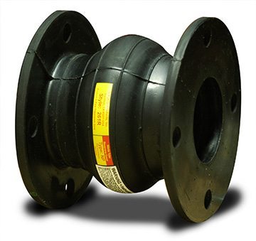
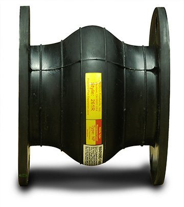
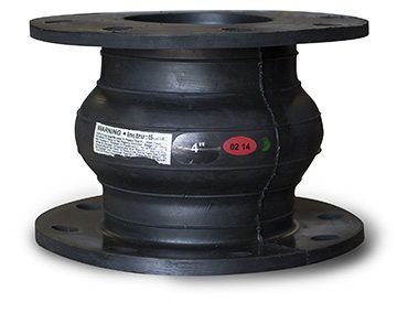
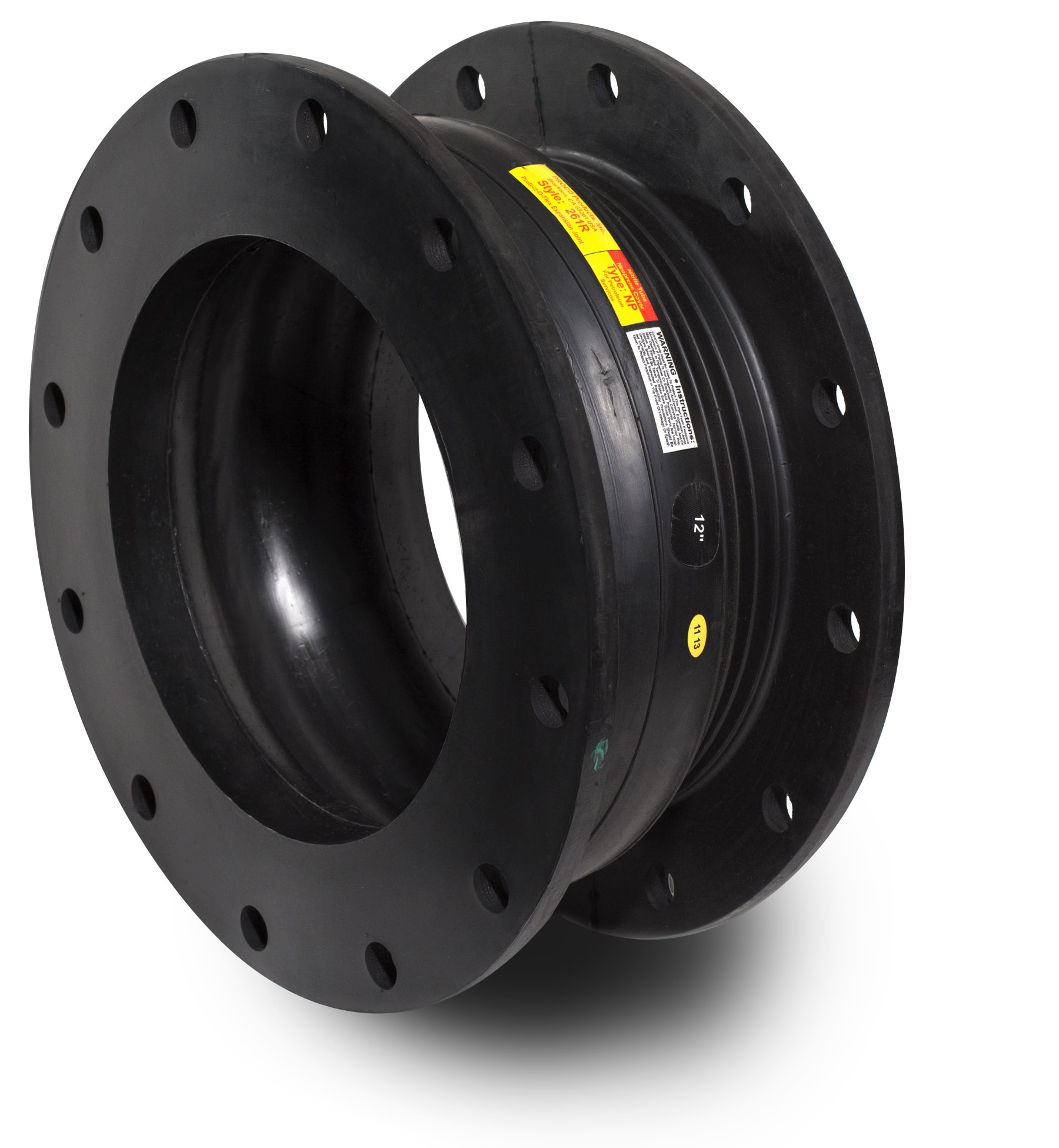
Proco Style 261R
Proco Style 261R molded wide arch expansion joints have the lowest spring rates of any expansion joints currently on the market. They also boast low forces to deflect, and are built to withstand even the most rigorous piping system configurations.
They allow for axial compression or axial extension, and lateral deflection as well as angular and torsional movements.
Some of the notable features and benefits of the Proco Style 261R are:
- Absorption of Directional Movement
- Absorption of Vibration, Noise and Shock
- Compensation for Misalignment
- Self-Cleaning Wide Arch
- Wide Choice of Flange Construction Materials Available
- Lighter Weight
For more information about the features and benefits of the Proco Style 261R, download our brochure.
For up-to-date pricing and availability information, contact Proco today.
Available Styles & Materials
| PROCO Material Code | Cover Elastomer | Tube Elastomer | Maximum Operating Temp. °F (°C) | Branding Label Color | F.S.A. Material Class |
|---|---|---|---|---|---|
| 261R/BB | Chlorobutyl | Chlorobutyl | 250 °F (121°C) | Black | STD. III |
| 261R/EE³ | EPDM | EPDM | 250 °F (121°C) | Red | STD. III |
| 261R/NH | Neoprene | CSM | 212 °F (100°C) | Green | STD. II |
| 261R/NN | Neoprene | Neoprene | 225 °F (107°C) | Blue | STD. II |
| 261R/NP³ | Neoprene | Nitrile | 225 °F (107°C) | Yellow | STD. II |
| 261R/NR | Neoprene | Natural | 180 °F (82°C) | White | STD. I |
Notes:
All products are reinforced with tire cord and metal materials.
1. Products mark (S) are in stock items.
2. All NN, NH & NP elastomer designated joints meet the Coast Guard Requirements and Conform to ASTM F 1123-87 and are marked accordingly.
|
ExpansionJoint |
Neutral Legnth Inch/ (mm) |
261R Movement Capability: From Neutral Postition¹ | Spring Rates | Operating Conditions² |
Weights in lbs³ |
||||||||||
| Axial Compression Inch / (mm) |
Axial Extension Inch/ (mm) |
Lateral Deflection Inch/ (mm) |
Angular Deflection (Degrees) |
Torsional Rotation (Degrees) |
Thrust Factor In2/ (cm2) |
Force Pounds for 1” Axial Compression lb/in/ (N/mm) |
Force Pounds for 1” Axial Extension lb/in /(N/mm) |
Force Pounds for 1” Lateral Deflection lb/in /(N/mm) |
Positive PSIG/ (Bar) | Vacuum Inches of Hg/ (mm of Hg) |
Expansion Joint | Retaining Ring Set |
Control Unit Assembly7 | ||
|
1.5 |
6
|
1.5
|
0.625 |
0.750 |
28 | 5 |
11.04 |
126 |
182 |
149 |
225 |
24 |
1.3 |
2.5 |
2.3 |
|
2 |
0.625 |
0.750 |
25 | 5 |
14.18 |
132 |
158 |
130 |
225 |
24 |
1.7 |
4.0 |
2.8 |
||
|
2.5 |
0.625 |
0.750 |
20 | 5 |
17.71 |
128 |
141 |
111 |
225 |
24 |
2.1 |
4.5 |
2.8 |
||
|
3 |
0.625 |
0.750 |
18 | 5 |
21.64 |
139 |
208 |
133 |
225 (15.5) |
24 |
2.4 |
5.5 |
2.8 |
||
|
4 |
0.625 |
0.750 |
14 | 4 |
30.66 |
110 |
180 |
105 |
225 |
24 |
3.2 |
6.0 |
2.8 |
||
|
5 |
0.625 |
0.750 |
13 | 4 |
41.26 |
143 |
190 |
136 |
225 |
24 |
3.6 |
8.5 |
4.0 |
||
|
6 |
0.625 |
0.750 |
12 | 4 |
53.43 |
136 |
166 |
147 |
225 |
24 |
4.9 |
9.5 |
4.0 |
||
|
8 |
0.625 |
0.750 |
12 | 4 |
82.47 |
226 |
230 |
210 |
210 |
24 |
7.7 |
14.5 |
8.0 |
||
|
10 |
8 |
2.25 |
0.750 |
1.0 |
12 | 4 |
135.13 |
248 |
381 |
281 |
210 |
24 |
13.9 |
17.0 |
10.0 |
|
12 |
0.750 |
1.0 |
11 | 4 |
179.46 |
378 |
493 |
409 |
210 |
24 |
19.5 |
24.5 |
10.0 |
||
|
14 |
0.750 |
1.0 |
11 | 3 |
230.08 |
423 |
592 |
497 |
150 |
24 |
22.7 |
27.0 |
12.0 |
||
|
16 |
0.750 |
1.0 |
10 | 3 |
286.98 |
432 |
606 |
509 |
150 |
24 |
26.8 |
33.5 |
15.0 |
||
|
18 |
0.750 |
1.0 |
8 | 3 |
350.15 |
543 |
761 |
690 |
150 |
24 |
29.5 |
34.0 |
16.0 |
||
|
20 |
0.750 |
1.0 |
8 | 3 |
419.61 |
628 |
829 |
776 |
150 |
24 |
31.8 |
38.0 |
16.0 |
||
NOTES:
1. Concurrent Movements – Concurrent movements are developed when two or more movements in a pipe system occur at the same time. If multiple movements exceed single arch design there may be a need for additional arches.
To perform calculation for concurrent movement when a pipe system design has more than one movement, please use the following formula:
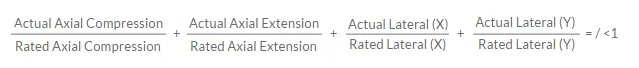
Calculation must be equal to or less than 1 for expansion joint to operate within concurrent movement capability.
2. Pressure rating is based on 194°F operating temperature. At higher temperature the pressure rating is slightly reduced. Vacuum rating is expressed when expansion joint is at neutral length.
3. Weights are approximate.
4. The degree of angular movement is based on the maximum rated extension.
5. Torsional movement is expressed when the expansion joint is at neutral length.
6. To determine “end thrust,” multiply thrust factor by operating pressure of system.
7. Limit rod control unit weight consists of one rod with washers, nuts and two limit rod plates. Multiply number of limit rods needed for the application (as specified in the Fluid Sealing Association’s Technical Handbook, 7.3 Edition or table 5 in this manual) to determine correct weights.
8. When limit/Control Units are required, use additional set of retaining rings on back side of mating flange when connecting to PVC, CPVC or FRP to improve stiffness.
| Standard Drilling for PROCO Rubber Expansion Joints | Thickness of Materials for PROCO Rubber Expansion Joints | Control Unit Plate Detail | |||||||||||||||||
|
Nominal |
Flange Dimensions² | Material Thickness for Bolt Length Requirements | |||||||||||||||||
|
Flange O.D. |
Bolt Circle Inch/(mm) | Number of Holes Inch/(mm) | Size of Holes Inch/(mm) |
Retaining Rings
|
Rubber
|
Adjacent³ Mating Flange Thickness |
Max Control Rod Plate Thickness
|
Control RodPlate O.D.
|
Maximum Rod Diameter Inch/(mm) | ||||||||||
| 1.5 | (40) | 5.00 | (127.00) | 3.88 | (98.55) | 4 | 0.625 | (15.9) | 0.375 | (9.53) | 0.375 | (9.53) | Customer to Specify Mating Flange Thickness |
0.375 | (9.53) | 9.125 | (231.8) | 0.625 | (15.9) |
| 2 | (50) | 6.00 | (152.40) | 4.75 | (120.65) | 4 | 0.750 | (19.05) | 0.375 | (9.53) | 0.375 | (9.53) | 0.375 | (9.53) | 10.125 | (257.2) | 0.625 | (15.9) | |
| 2.5 | (65) | 7.00 | (177.80) | 5.50 | (139.70) | 4 | 0.750 | (19.05) | 0.375 | (9.53) | 0.375 | (9.53) | 0.375 | (9.53) | 11.125 | (282.6) | 0.625 | (15.9) | |
| 3 | (80) | 7.50 | (190.50) | 6.00 | (152.40) | 4 | 0.750 | (19.05) | 0.375 | (9.53) | 0.375 | (9.53) | 0.375 | (9.53) | 11.625 | (295.3) | 0.625 | (15.9) | |
| 4 | (100) | 9.00 | (228.60) | 7.50 | (190.50) | 8 | 0.750 | (19.05) | 0.375 | (9.53) | 0.375 | (9.53) | 0.375 | (9.53) | 13.125 | (333.4) | 0.625 | (15.9) | |
| 5 | (125) | 10.00 | (254.00) | 8.50 | (215.90) | 8 | 0.875 | (22.23) | 0.375 | (9.53) | 0.375 | (9.53) | 0.500 | (12.70) | 14.125 | (358.8) | 0.625 | (15.9) | |
| 6 | (150) | 11.00 | (279.40) | 9.50 | (241.30) | 8 | 0.875 | (22.23) | 0.375 | (9.53) | 0.375 | (9.53) | 0.500 | (12.70) | 15.125 | (384.2) | 0.625 | (15.9) | |
| 8 | (200) | 13.50 | (342.90) | 11.75 | (298.45) | 8 | 0.875 | (22.23) | 0.375 | (9.53) | 0.390 | (10) | 0.750 | (19.05) | 19.125 | (485.8) | 1.000 | (25.4) | |
| 10 | (250) | 16.00 | (406.40) | 14.25 | (361.95) | 12 | 1.000 | (25.40) | 0.375 | (9.53) | 0.625 | (15.88) | 0.750 | (19.05) | 21.625 | (549.3) | 1.000 | (25.4) | |
| 12 | (300) | 19.00 | (482.60) | 17.00 | (431.80) | 12 | 1.000 | (25.40) | 0.375 | (9.53) | 0.625 | (15.88) | 0.750 | (19.05) | 24.625 | (625.5) | 1.000 | (25.4) | |
| 14 | (350) | 21.00 | (533.40) | 18.75 | (476.25) | 12 | 1.125 | (28.58) | 0.375 | (9.53) | 0.625 | (15.88) | 0.750 | (19.05) | 26.625 | (676.3) | 1.000 | (25.4) | |
| 16 | (400) | 23.50 | (596.90) | 21.25 | (539.75) | 16 | 1.125 | (28.58) | 0.375 | (9.53) | 0.625 | (15.88) | 0.750 | (19.05) | 30.125 | (765.2) | 1.250 | (31.8) | |
| 18 | (450) | 25.00 | (635.00) | 22.75 | (577.85) | 16 | 1.250 | (31.75) | 0.375 | (9.53) | 0.625 | (15.88) | 0.750 | (19.05) | 31.625 | (803.3) | 1.250 | (31.8) | |
| 20 | (500) | 27.50 | (698.50) | 25.00 | (635.00) | 20 | 1.250 | (31.75) | 0.375 | (9.53) | 0.625 | (15.88) | 0.750 | (19.05) | 34.125 | (866.8) | 1.250 | (31.8) | |
Metric Conversion Formula: Nominal I.D.: in. x 25 = mm; Dimensions/Thickness’: in. x 25.4 = mm.
Notes:
1. Limit/Control Rod length is determined by neutral length of rubber expansion joint, rated extension, control rod plate thickness, mating flange thickness and number of nuts. Consult PROCO for rod lengths.
2. Flange Dimensions shown are in accordance with ANSI B16.1 and ANSI B16.5 Class 125/150, AWWA C-207-07, Tbl 2 and 3 – Class D, Table 4 – Class E. Hole size shown is 1/8” larger than AWWA Standard.
3. Adjacent mating flange thickness is required to determine overall rod length and compression sleeve length (if required).
4. Plate thickness is based on a maximum width PROCO would use to design a Limit/Control Rod plate.
5. Flat Washers required at ring splits and are by others.
6. Control rod plate O.D. installed dimension is based on a maximum O.D. Proco would supply.
7. Control rod diameter is based on a maximum diameter Proco would use to design a control rod.
|
Nominal |
Maximum Surge or Test |
||||
|
Number of Control Rods |
|||||
| 2 | 4 | 6 | 8 | ||
| 2 | (50) | 661 | • | • | • |
| 2.5 | (65) | 529 | • | • | • |
| 3 | (75) | 441 | • | • | • |
| 4 | (100) | 311 | 622 | • | • |
| 5 | (125) | 235 | 470 | • | • |
| 6 | (150) | 186 | 371 | • | • |
| 8 | (200) | 163 | 326 | • | • |
| 10 | (250) | 163 | 325 | 488 | • |
| 12 | (300) | 160 | 320 | 481 | • |
| 14 | (350) | 112 | 223 | 335 | • |
| 16 | (400) | 113 | 227 | 340 | 453 |
| 18 | (450) | 94 | 187 | 281 | 375 |
| 20 | (500) | 79 | 158 | 236 | 315 |
Notes:
Pressures listed above do not relate to the actual design pressure of the expansion joint products, but are the maximum surge or pressure for a specific control rod nominal pipe size.
A control rod unit consists of limit rods, tie rods, or compression sleeves, and a control unit assembly is a system of two or more control rod units placed across an expansion joint from flange to flange. Their purpose is to minimize possible damage caused by possible excessive motion of a pipeline. Control unit assemblies can be set at the maximum allowable expansion and / or contraction of the rubber expansion joint.
When used properly, control unit assemblies serve as additional safety enhancements, and can minimize possible damage due to adjacent equipment.
Rubber expansion joints should be installed between two fixed anchor points in a piping system. When proper anchoring can’t be provided, control units are required. When an un-anchored piping system is encountered, nuts should be tightened securely against the rod plate, to prevent over-extension due to pressure thrust caused by the expansion joint.
Listed below are three control unit configurations supplied by PROCO, that are commonly used with rubber expansion joints in piping systems.
- Figure 1: Limit Rod. A limit rod control unit configuration will allow an expansion joint to lengthen to a predetermined extension setting. Spherical washers can also be furnished, upon request, to prevent any “nut to plate” binding during offset.
- Figure 2: Limit / Control Rod. This type of configuration is used to allow specified pipe expansion (expansion joint axial compression) and pipe contraction (expansion joint axial extension) movements. Spherical washers can also be furnished, upon request, to prevent any “nut to plate” binding during offset.
- Figure 3: Compression Sleeve. A compression sleeve configuration is used to allow for specified pipe expansion (expansion joint axial compression) and pipe contraction (expansion joint extension) movements. PROCO will supply each compression sleeve equipped to prevent any axial movement, unless otherwise specified at the time of purchase. Spherical washers can also be furnished, upon request, to prevent any “nut to plate” binding during offset.
For more information on PROCO control unit specifications, download our Series 261R Brochure.
For up-to-date pricing and availability information, contact PROCO today.
Proco Style 261R molded wide arch expansion joints are specifically designed for use with plastic or FRP piping systems. They’re a suitable replacement for standard spool-type expansion joints, and posess exceptionally low spring rates compared to their conventional counterparts. With low forces to compress, extend, or laterally offset, these expansion joints can be used on plastic or FRP pipes, pumps, valves or tanks without fear of the expansion joint being stronger than the plastic or FRP pipe, pump, valve or tank flanges.
When pairing Style 261R expansion joints with standard control units utilizing control/gusset plates, a stiffener ring is required, in order to reinforce the mating flange. This technique distributes the pressure thrust loads experienced by the control units across the flange, as opposed to a standard installation where the loads are localized at the points of contact between the control/gusset plate and flange.
For more detailed information, download the Proco Series 261R Brochure.