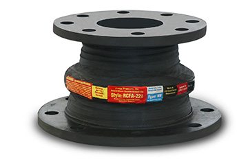
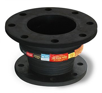
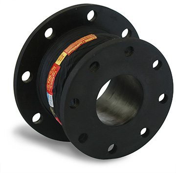
Proco Style RC -231
Proco Style RC-231 wide arch concentric rubber expansion joints are built to withstand even the most rigorous piping system configurations. They allow for axial compression or axial extension, and lateral deflection as well as angular and torsional movements.
Some of the notable features and benefits of the Proco Style RC-231 are:
- Absorption of Directional Movement
- Reduced Turbulence or Material Entrapment
- Absorption of Vibration, Noise and Shock
- Compensation for Misalignment
- Wide Service Range and Lighter Weight
For more information about the features and benefits of the Proco Style RC-231, download our brochure.
For up-to-date pricing and availability information, contact PROCO today.


Available Styles & Materials
| PROCO Material Code | Cover 1,2 Elastomer | Tube Elastomer | Maximum Operating Temp. °F (°C) | Branding Label Color | F.S.A. Material Class |
|---|---|---|---|---|---|
| BB | Chlorobutyl | Chlorobutyl | 250 °F (121°C) | Black | STD. III |
| EE | EPDM | EPDM | 250 °F (121°C) | Red | STD. III |
| EQ | EPDM | FDA-EPDM | 250 °F (121°C) | Red³ | STD. II |
| NH | Neoprene | CSM | 212 °F (100°C) | Green | STD. II |
| NN | Neoprene | Neoprene | 225 °F (107°C) | Blue | STD. II |
| NF | Neoprene | FDA-Neoprene | 225 °F (107°C) | Blue³ | STD. II |
| NP | Neoprene | Nitrile | 212 °F (100°C) | Yellow | STD. II |
| NR | Neoprene | Natural Rubber | 180 °F (82°C) | White | STD. I |
Notes:
All products are reinforced with Polyester Tire Cord
1. Expansion Joint “Cover” can be coated with CSM UV Resistant Coating.
2. All NN & NP elastomer designated joints meet the Coast Guard Requirements and conform to ASTM F 1123-87 and are marked accordingly.
3. Branding Label will be marked as “Food Grade”.
4. All elastomers above are not intended for steam service.
| Concentric Joint Size | Neutral Length | RC-231 Movement Capability 1 From Neutral Position: | Operating 2 Conditions |
Weights3 |
||||||||
|
Nominal |
Min. |
Max. |
Axial Compression |
Axial Extension |
Lateral Deflection |
Angular 4 Deflection |
Torsional 5 Rotation |
Thrust Factor 6 In2 / (cm2) |
Positive PSIG / (Bar) | Vacuum In. 7 of Hg / (mm of Hg) |
Expansion Joint / Rings | Limit Rods8 |
| 2 x 1 | 8 | 18 |
1.0 |
0.5 |
0.5 |
25.0 | 2.0 |
4.83 |
200 |
26 |
5.0 |
7.0 |
| 2 x 1.5 | 8 | 18 |
1.0 |
0.5 |
0.5 |
25.0 | 2.0 |
5.85 |
200 |
26 |
6.0 |
7.0 |
| 2.5 x 1.5 | 8 | 18 |
1.0 |
0.5 |
0.5 |
20.0 | 2.0 |
6.97 |
200 |
26 |
6.0 |
8.0 |
| 2.5 x 2 | 8 | 18 |
1.0 |
0.5 |
0.5 |
20.0 | 2.0 |
8.19 |
200 |
26 |
6.0 |
8.0 |
| 3 x 1 | 8 | 18 |
1.4 |
0.7 |
0.5 |
24.0 | 2.0 |
6.97 |
200 |
26 |
7.0 |
8.0 |
| 3 x 1.5 | 8 | 18 |
1.4 |
0.7 |
0.5 |
24.0 | 2.0 |
8.19 |
200 |
26 |
8.0 |
8.0 |
| 3 x 2 | 8 | 18 |
1.4 |
0.7 |
0.5 |
24.0 | 2.0 |
9.51 |
200 |
26 |
9.0 |
8.0 |
| 3 x 2.5 | 8 | 18 |
1.4 |
0.7 |
0.5 |
24.0 | 2.0 |
10.92 |
200 |
26 |
9.0 |
8.0 |
| 4 x 2 | 8 | 18 |
1.4 |
0.7 |
0.5 |
18.0 | 2.0 |
12.43 |
200 |
26 |
10.0 |
8.0 |
| 4 x 2.5 | 8 | 18 |
1.4 |
0.7 |
0.5 |
18.0 | 2.0 |
14.05 |
200 |
26 |
11.0 |
8.0 |
| 4 x 3 | 8 | 18 |
1.4 |
0.7 |
0.5 |
18.0 | 2.0 |
15.76 |
200 |
26 |
12.0 |
8.0 |
| 5 x 3 | 8 | 18 |
1.6 |
0.8 |
0.5 |
17.0 | 2.0 |
21.06 |
190 |
26 |
15.0 |
12.0 |
| 5 x 4 | 8 | 18 |
1.6 (41) |
0.8 (20) |
0.5 (13) |
17.0 | 2.0 |
25.33 (163) |
190 (13) |
26(660) |
16.0 (7.3) |
12.0 (5.4) |
| 6 x 2 | 8 | 18 |
1.6 (41) |
0.8 (20) |
0.5 (13) |
14.0 | 2.0 |
21.06 (136) |
190 (13) |
26 (660) |
15.0 (6.8) |
14.0 (6.4) |
| 6 x 2.5 | 8 | 18 |
1.6 |
0.8 |
0.5 |
14.0 | 2.0 |
23.15 |
190 |
26 |
15.0 |
14.0 |
| 6 x 3 | 8 | 18 |
1.6 |
0.8 |
0.5 |
14.0 | 2.0 |
25.33 |
190 |
26 |
17.0 |
14.0 |
| 6 x 4 | 8 | 18 |
1.6 |
0.8 |
0.5 |
14.0 | 2.0 |
29.98 |
190 |
26 |
17.0 |
14.0 |
| 6 x 5 | 8 | 18 |
1.6 |
0.8 |
0.5 |
14.0 | 2.0 |
35.03 |
190 |
26 |
18.0 |
14.0 |
| 8 x 3 | 8 | 18 |
1.6 |
0.8 |
0.5 |
11.0 | 2.0 |
35.03 |
190 |
26 |
19.0 |
22.0 |
| 8 x 4 | 8 | 18 |
1.6 |
0.8 |
0.5 |
11.0 | 2.0 |
40.47 |
190 |
26 |
19.0 |
21.0 |
| 8 x 5 | 8 | 18 |
1.6 (41) |
0.8 (20) |
0.5 (13) |
11.0 | 2.0 |
46.30 (299) |
190 (13) |
26 (660) |
20.0 (9.1) |
22.0 (10.0) |
| 8 x 6 | 8 | 18 |
1.6 |
0.8 |
0.5 |
11.0 | 2.0 |
52.53 |
190 |
26 |
21.0 |
23.0 |
| 10 x 5 | 10 | 18 |
1.6 |
0.8 |
0.5 |
8.0 | 2.0 |
59.14 |
190 |
26 |
25.0 |
31.0 |
| 10 x 6 | 10 | 18 |
1.6 |
0.8 |
0.5 |
8.0 | 2.0 |
66.15 |
190 |
26 |
26.0 |
31.0 |
| 10 x 8 | 10 | 18 |
1.6 |
0.8 |
0.5 |
8.0 | 2.0 |
81.35 |
190 |
26 |
30.0 |
32.0 |
| 12 x 6 | 10 | 18 |
1.6 |
0.8 |
0.5 |
7.0 | 2.0 |
84.50 |
190 |
26 |
35.0 |
35.0 |
| 12 x 8 | 10 | 18 |
1.6 |
0.8 |
0.5 |
7.0 | 2.0 |
101.57 |
190 |
26 |
39.0 |
34.0 |
| 12 x 10 | 10 | 18 |
1.6 |
0.8 |
0.5 |
7.0 | 2.0 |
120.22 |
190 |
26 |
42.0 |
29.0 |
| 14 x 8 | 10 | 18 |
1.6 |
0.8 |
0.5 |
6.0 | 2.0 |
120.22 |
130 |
26 |
45.0 |
34.0 |
| 14 x 10 | 10 | 18 |
1.6 |
0.8 |
0.5 |
6.0 | 2.0 |
140.43 |
130 |
26 |
48.0 |
38.0 |
| 14 x 12 | 10 | 18 |
1.6 |
0.8 |
0.5 |
6.0 | 2.0 |
162.21 |
130 |
26 |
55.0 |
31.0 |
| 16 x 10 | 10 | 18 |
1.6 |
0.8 |
0.5 |
5.0 | 2.0 |
162.21 |
115 |
26 |
54.0 |
45.0 |
| 16 x 12 | 10 | 18 |
1.6 |
0.8 |
0.5 |
5.0 | 2.0 |
185.57 |
115 |
26 |
60.0 |
42.0 |
| 16 x 14 | 10 | 18 |
1.6 |
0.8 |
0.5 |
5.0 | 2.0 |
210.49 |
115 |
26 |
62.0 |
43.0 |
| 18 x 12 | 10 | 18 |
1.6 |
0.8 |
0.5 |
5.0 | 2.0 |
210.49 |
115 |
26 |
64.0 |
48.0 |
| 18 x 14 | 10 | 18 |
1.6 |
0.8 |
0.5 |
5.0 | 2.0 |
236.98 |
115 |
26 |
66.0 |
43.0 |
| 18 x 16 | 10 | 18 |
1.6 |
0.8 |
0.5 |
5.0 | 2.0 |
265.05 |
115 |
26 |
70.0 |
39.0 |
NOTES:
1. Concurrent Movements – Concurrent movements are developed when two or more movements in a pipe system occur at the same time.
If multiple movements exceed single arch design there may be a need for additional arches.
To perform calculation for concurrent movement when a pipe system design has more than one movement, please use the following formula:
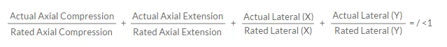
Calculation must be equal to or less than 1 for expansion joint to operate within concurrent movement capability.
2. Pressure rating is based on 170˚ F operating temperature with a 4:1 safety factor. At higher temperatures, the pressure rating is reduced slightly. Hydrostatic testing at 1.5 times rated maximum catalogue pressure or design working pressure of pipe system for 10 minutes is available upon request.
3. Weights are approximate and vary due to length.
4. The degree of angular movement is based on the maximum rated extension.
5. Torsional movement is expressed when the expansion joint is at neutral length.
6. Calculation of Thrust (Thrust Factor). When expansion joints are installed in the pipeline, the static portion of the thrust is calculated as a product of the area of the I.D. of the arch of the expansion joint times the maximum pressure (design, test or surge) that will occur in the line. The result is a force expressed in pounds. Take design, surge or test pressure X thrust factor to calculate end thrust. For filled arch configuration use the I.D. of the pipe (D)2 to calculate end thrust.
7. Parts listed at 26” Hg / 660 mm Hg vacuum. Vacuum rating is based on neutral installed length, without external load. Products should not be installed “extended” on vacuum applications.
8. Limit rod unit weight consists of one rod with washers, nuts, and two limit rod plates. Multiply number of limit rods needed for the application (as specified in the Fluid Sealing Association’s Technical Handbook, Seventh Edition or table 4 in this manual) to determine correct weights.
9. For plastic pipe systems utilizing the series RC, consult Proco for design considerations.
10. Larger sizes not shown in brochure are available upon request.
| Joint Size | Neutral Length | RC & RE 221 Movement Capability 1 from Neutral Position | Operating2 Conditions |
Weights3 |
||||||||
|
Nominal |
RC |
RE |
Axial Compression |
Axial Extension |
Lateral Deflection |
Angular4 Deflection Degrees | Torsional5 Rotation Degrees |
Thrust Factor6 |
Positive PSIG / (Bar) |
Vacuum In. of 7 |
Expansion Joint/Rings | Limit Rods 8 |
| 2 x 1 | 6 | 6 |
0.5 |
.25 |
0.5 |
18.4 | 2.0 |
12.69 |
200 |
26 |
5.0 |
7.0 |
| 2 x 1.5 | 6 | 6 |
0.5 |
.25 |
0.5 |
15.9 | 2.0 |
14.32 |
200 |
26 |
6.0 |
7.0 |
| 2 x 1.5 | X | 7 |
0.5 |
.25 |
0.5 |
14.1 | 2.0 |
16.04 |
200 |
26 |
6.0 |
7.0 |
| 2.5 x 1.5 | 6 | 6 |
0.5 |
.25 |
0.5 |
14.1 | 2.0 |
16.04 |
200 |
26 |
6.0 |
8.0 |
| 2.5 x 2 | 6 | 6 |
0.5 |
.25 |
0.5 |
12.5 | 2.0 |
17.87 |
200 |
26 |
6.0 |
8.0 |
| 2.5 x 2 | X | 7 |
0.5 |
.25 |
0.5 |
12.5 | 2.0 |
17.87 |
200 |
26 |
6.0 |
8.0 |
| 3.0 x 1.5 | 6 | 6 |
0.5 |
.25 |
0.5 |
12.5 | 2.0 |
17.87 |
200 |
26 |
8.0 |
8.0 |
| 3.0 x 2 | 6 | 6 |
0.5 |
.25 |
0.5 |
11.3 | 2.0 |
19.79 |
200 |
26 |
9.0 |
8.0 |
| 3.0 x 2.5 | 6 | 6 |
0.5 |
.25 |
0.5 |
10.3 | 2.0 |
21.81 |
200 |
26 |
9.0 |
8.0 |
| 4.0 x 2 | 6 | 6 |
0.5 |
.25 |
0.5 |
9.5 | 2.0 |
23.93 |
200 |
26 |
10.0 |
8.0 |
| 4.0 x 2 | 7 | 7 |
0.5 |
.25 |
0.5 |
9.5 | 2.0 |
23.93 |
200 |
26 |
10.0 |
8.0 |
| 4 x 2.5 | 6 | 6 |
0.5 |
.25 |
0.5 |
8.7 | 2.0 |
26.14 |
200 |
26 |
11.0 |
8.0 |
| 4 x 2.5 | 7 | 7 |
0.5 |
.25 |
0.5 |
8.7 | 2.0 |
26.14 |
200 |
26 |
11.0 |
8.0 |
| 4 x 3 | 6 | 6 |
0.5 |
.25 |
0.5 |
8.1 | 2.0 |
28.46 |
200 |
26 |
12.0 |
8.0 |
| 4 x 3 | 7 | 7 |
0.5 |
.25 |
0.5 |
8.1 | 2.0 |
28.46 |
190 |
26 |
12.0 |
8.0 |
| 5 x 3 | 6 | X |
0.5 |
.25 |
0.5 |
7.1 | 2.0 |
33.38 |
190 |
26 |
15.0 |
12.0 |
| 5 x 4 | 6 | 6 |
0.5 |
.25 |
0.5 (13) |
6.3 | 2.0 |
38.70 (250) |
190 (13) |
26 (660) |
16.0 (7.3) |
12.0 (5.4) |
| 6 x 2.5 | 6 | X |
0.5 |
.25 |
0.5 |
6.7 | 2.0 |
35.99 |
190 |
26 |
15.0 |
14.0 |
| 6 x 3 | 6 | 6 |
0.5 |
.25 |
0.5 |
6.3 | 2.0 |
38.70 |
190 |
26 |
17.0 |
14.0 |
| 6 x 4 | 6 | 6 |
0.5 |
.25 |
0.5 |
5.7 | 2.0 |
44.41 |
190 |
26 |
17.0 |
14.0 |
| 6 x 5 | 6 | 6 |
0.5 |
.25 |
0.5 |
5.2 | 2.0 |
50.51 |
190 |
26 |
18.0 |
14.0 |
| 8 x 3 | 6 | X |
.75 |
.375 |
0.5 |
7.8 | 2.0 |
56.64 |
190 |
26 |
19.0 |
22.0 |
| 8 x 4 | 6 | 6 |
.75 |
.375 |
0.5 |
7.1 | 2.0 |
63.51 |
190 |
26 |
19.0 |
21.0 |
| 8 x 5 | 6 | X |
.75 |
.375 |
0.5 |
6.6 | 2.0 |
70.77 |
190 |
26 |
20.0 |
22.0 |
| 8 x 6 | 6 | 6 |
.75 |
.375 |
0.5 |
6.1 | 2.0 |
78.42 |
190 |
26 |
21.0 |
23.0 |
| 10 x 5 | 8 | X |
.75 |
.375 |
0.5 |
5.7 | 2.0 |
86.46 |
190 |
26 |
25.0 |
31.0 |
| 10 x 6 | 8 | 8 |
.75 |
.375 |
0.5 |
5.4 | 2.0 |
94.90 |
190 |
26 |
26.0 |
31.0 |
| 10 x 6 | X | 9 |
.75 |
.375 |
0.5 |
5.4 | 2.0 |
94.90 |
190 |
26 |
26.0 |
31.0 |
| 10 x 8 | 6 | 6 |
.75 |
.375 |
0.5 |
4.8 | 2.0 |
112.95 |
190 |
26 |
30.0 |
32.0 |
| 10 x 8 | 8 | 8 |
.75 |
.375 |
0.5 |
4.8 | 2.0 |
112.95 |
190 |
26 |
30.0 |
32.0 |
| 12 x 6 | 8 | X |
.75 |
.375 |
0.5 |
4.8 | 2.0 |
112.95 |
190 |
26 |
35.0 |
35.0 |
| 12 x 8 | 6 | 8 |
.75 |
.375 |
0.5 |
4.3 | 2.0 |
132.57 |
190 |
26 |
39.0 |
34.0 |
| 12 x 8 | 8 | X |
.75 |
.375 |
0.5 |
4.3 | 2.0 |
132.57 |
190 |
26 |
39.0 |
34.0 |
| 12 x 10 | 8 | 8 |
.75 (19) |
.375 (9.5) |
0.5 (13) |
3.9 | 2.0 |
153.77 |
190 |
26 |
42.0 |
29.0 |
| 14 x 8 | 8 | X |
.75 |
.375 |
0.5 |
3.9 | 2.0 |
177.09 |
130 |
26 |
45.0 |
34.0 |
| 14 x 10 | 8 | 8 |
.75 |
.375 |
0.5 |
3.6 | 2.0 |
201.46 |
130 |
26 |
48.0 |
38.0 |
| 14 x 10 | X | 10 |
.75 |
.375 |
0.5 |
3.6 | 2.0 |
201.46 |
130 |
26 |
48.0 |
38.0 |
| 14 x 12 | 8 | 8 |
.75 |
.375 |
0.5 |
3.3 | 2.0 |
227.40 |
130 |
26 |
55.0 |
31.0 |
| 16 x 10 | 8 | X |
.75 |
.375 |
0.5 |
3.3 | 2.0 |
227.40 |
110 |
26 |
54.0 |
45.0 |
| 16 x 12 | 8 | 10 |
.75 |
.375 |
0.5 |
3.1 | 2.0 |
254.92 |
110 |
26 |
60.0 |
42.0 |
| 16 x 14 | 8 | 8 |
.75 |
.375 |
0.5 |
2.9 | 2.0 |
284.00 |
110 |
26 |
62.0 |
43.0 |
| 18 x 12 | 8 | X |
.75 |
.375 |
0.5 |
2.9 | 2.0 |
284.00 |
110 |
26 |
64.0 |
48.0 |
| 18 x 14 | 8 | X |
.75 |
.375 |
0.5 |
2.7 | 2.0 |
314.65 |
118 |
26 |
66.0 |
43.0 |
| 18 x 16 | 8 | 8 |
.75 |
.375 |
0.5 |
2.5 | 2.0 |
346.88 |
110 |
26 |
70.0 |
39.0 |
NOTES:
1. Concurrent Movements – Concurrent movements are developed when two or more movements in a pipe system occur at the same time.
If multiple movements exceed single arch design there may be a need for additional arches.
To perform calculation for concurrent movement when a pipe system design has more than one movement, please use the following formula:
Calculation must be equal to or less than 1 for expansion joint to operate within concurrent movement capability.
2. Pressure rating is based on 170˚ F operating temperature with a 4:1 safety factor. At higher temperatures, the pressure rating is reduced slightly. Hydrostatic testing at 1.5 times rated maximum catalogue pressure or design working pressure of pipe system for 10 minutes is available upon request.
3. Weights are approximate and vary due to length.
4. The degree of angular movement is based on the maximum rated extension.
5. Torsional movement is expressed when the expansion joint is at neutral length.
6. Calculation of Thrust (Thrust Factor). When expansion joints are installed in the pipeline, the static portion of the thrust is calculated as a product of the area of the I.D. of the arch of the expansion joint times the maximum pressure (design, test or surge) that will occur in the line. The result is a force expressed in pounds. Take design, surge or test pressure X thrust factor to calculate end thrust. For filled arch configuration use the I.D. of the pipe (D)2 to calculate end thrust.
7. Parts listed at 26” Hg / 660 mm Hg vacuum. Vacuum rating is based on neutral installed length, without external load. Products should not be installed “extended” on vacuum applications.
8. Limit rod unit weight consists of one rod with washers, nuts, and two limit rod plates. Multiply number of limit rods needed for the application (as specified in the Fluid Sealing Association’s Technical Handbook, Seventh Edition or table 4 in this manual) to determine correct weights.
9. For plastic pipe systems utilizing the series RC/RE, consult Proco for design considerations.
10. Larger sizes not shown in brochure are available upon request.
| Flange Drillings |
Thickness of Materials for |
Control Unit |
|||||||||||||||
|
Joint Size |
Standard Drilling for PROCO Series RC or RE² Rubber Expansion Joints 125/150# Flange Dimensions | Material Thickness¹ for Bolt Length Requirements | |||||||||||||||
| Large End | Small End |
Concentric & Eccentric |
Retaining Rings Thickness Inch/(mm) |
Large End |
Small End | Adjacent Mating Flange Thickness | Large End
|
Small End | Control Rod Plate O.D. Inch/(mm) | Maximum Rod Diameter Inch/(mm) | |||||||
|
Nominal |
Flange O.D. |
Bolt Circle |
No. |
Size of Holes |
Flange O.D. |
Bolt Circle |
No. |
Size of Holes |
Rubber Flange Thickness Inch/(mm) | Max. Control Rod Plate Thickness Inch/(mm) | |||||||
| 2 X 1 |
6.00 |
4.750 |
4 |
0.750 |
4.25 |
3.125 |
4 |
0.625 |
Refer to Tables 2,3 &4 |
0.375 |
0.472 |
0.472 |
Customer to Specify Flange Thickness |
0.375 |
0.375 |
10.125 |
0.625 |
| 2 X 1.5 |
6.00 |
4.750 |
4 |
0.750 |
5.00 |
3.875 |
4 |
0.625 |
0.375 |
0.472 |
0.472 |
0.375 |
0.375 |
10.125 |
0.625 |
||
| 2.5 X 1.5 |
7.00 |
5.500 |
4 |
0.750 |
5.00 |
3.875 |
4 |
0.625 |
0.375 |
0.472 |
0.472 |
0.375 |
0.375 |
11.125 |
0.625 |
||
| 2.5 X 2 |
7.00 |
5.500 |
4 |
0.750 |
6.00 |
4.750 |
4 |
0.750 |
0.375 |
0.472 |
0.472 |
0.375 |
0.375 |
11.125 |
0.625 |
||
| 3.0 X 1.5 |
7.50 |
6.000 |
4 |
0.750 |
5.00 |
3.875 |
4 |
0.625 |
0.375 |
0.472 |
0.472 |
0.375 |
0.375 |
11.625 |
0.625 |
||
| 3.0 X 2 |
7.50 |
6.000 |
4 |
0.750 |
6.00 |
4.750 |
4 |
0.750 |
0.375 |
0.472 |
0.472 |
0.375 |
0.375 |
11.625 |
0.625 |
||
| 3.0 X 2.5 |
7.50 |
6.000 |
4 |
0.750 |
7.00 |
5.500 |
4 |
0.750 |
0.375 |
0.472 |
0.472 |
0.375 |
0.375 |
11.625 |
0.625 |
||
| 4.0 X 2 |
9.00 |
7.500 |
8 |
0.750 |
6.00 |
4.750 |
4 |
0.750 |
0.375 |
0.472 |
0.472 |
0.375 |
0.375 |
13.125 |
0.625 |
||
| 4 X 2.5 |
9.00 |
7.500 |
8 |
0.750 |
7.00 |
5.500 |
4 |
0.750 |
0.375 |
0.472 |
0.472 |
0.375 |
0.375 |
13.125 |
0.625 |
||
| 4 X 3 |
9.00 |
7.500 |
8 |
0.750 |
7.50 |
6.00 |
4 |
0.750 |
0.375 |
0.472 |
0.472 |
0.375 |
0.375 |
13.125 |
0.625 |
||
| 5 X 3 |
10.00 |
8.500 |
8 |
0.875 |
7.50 |
6.00 |
4 |
0.750 |
0.375 |
0.551 |
0.472 |
0.500 |
0.375 |
14.125 |
0.625 |
||
| 5 X 4 |
10.00 |
8.500 |
8 |
0.875 |
9.00 |
7.50 |
4 |
0.750 |
0.375 |
0.551 |
0.472 |
0.500 |
0.375 |
14.125 |
0.625 |
||
| 6 X 2.5 |
11.00 |
9.500 |
8 |
0.875 |
7.00 |
5.500 |
4 |
0.750 |
0.375 |
0.551 |
0.472 |
0.500 |
0.375 |
15.125 |
0.625 |
||
| 6 X 3 |
11.00 |
9.500 |
8 |
0.875 |
7.50 |
6.00 |
4 |
0.750 |
0.375 |
0.551 |
0.472 |
0.500 |
0.375 |
15.125 |
0.625 |
||
| 6 X 4 |
11.00 |
9.500 |
8 |
0.875 |
9.00 |
7.50 |
8 |
0.750 |
0.375 |
0.551 |
0.472 |
0.500 |
0.472 |
15.125 |
0.625 |
||
| 6 X 5 |
11.00 |
9.500 |
8 |
0.875 |
10.00 |
8.500 |
8 |
0.875 |
0.375 |
0.551 |
0.472 |
0.500 |
0.551 |
15.125 |
0.625 |
||
| 8 X 3 |
13.50 |
11.75 |
8 |
0.875 |
7.50 |
6.00 |
4 |
0.750 |
0.375 |
0.630 |
0.472 |
0.750 |
0.472 |
19.125 |
1.000 |
||
| 8 X 4 |
13.50 |
11.75 |
8 |
0.875 |
9.00 |
7.50 |
8 |
0.750 |
0.375 |
0.630 |
0.472 |
0.750 |
0.472 |
19.125 |
1.000 |
||
| 8 X 5 |
13.50 |
11.75 |
8 |
0.875 |
10.00 |
8.500 |
8 |
0.875 |
0.375 |
0.630 |
0.551 |
0.750 |
0.551 |
19.125 |
1.000 |
||
| 8 X 6 |
13.50 |
11.75 |
8 |
0.875 |
11.00 |
9.500 |
8 |
0.875 |
0.375 |
0.630 |
0.551 |
0.750 |
0.551 |
19.125 |
1.000 |
||
| 10 X 5 |
16.00 |
14.25 |
12 |
1.000 |
10.00 |
8.500 |
8 |
0.875 |
0.375 |
0.630 |
0.551 |
0.750 |
0.551 |
21.125 |
1.000 |
||
| 10 X 6 |
16.00 |
14.25 |
12 |
1.000 |
11.00 |
9.500 |
8 |
0.875 |
0.375 |
0.630 |
0.551 |
0.750 |
0.551 |
21.125 |
1.000 |
||
| 10 X 8 |
16.00 |
14.25 |
12 |
1.000 |
13.50 |
11.750 |
8 |
0.875 |
0.375 |
0.630 |
0.630 |
0.750 |
0.631 |
21.125 |
1.000 |
||
| 12 X 6 |
19.00 |
17.00 |
12 |
1.000 |
11.00 |
9.500 |
8 |
0.875 |
0.375 |
0.748 |
0.630 |
0.750 |
0.551 |
24.625 |
1.000 |
||
| 12 X 8 |
19.00 |
17.00 |
12 |
1.000 |
13.50 |
11.750 |
8 |
0.875 |
0.375 |
0.748 |
0.630 |
0.750 |
0.631 |
24.625 |
1.000 |
||
| 12 X 10 |
19.00 |
17.00 |
12 |
1.000 |
16.00 |
14.250 |
12 |
1.000 |
0.375 |
0.748 |
0.630 |
0.750 |
0.631 |
24.625 |
1.000 |
||
| 14 X 8 |
21.00 |
18.75 |
12 |
1.125 |
13.50 |
11.750 |
8 |
0.875 |
0.375 |
0.866 |
0.630 |
0.750 |
0.631 |
26.625 |
1.000 |
||
| 14 X 10 |
21.00 |
18.75 |
12 |
1.125 |
16.00 |
14.250 |
12 |
1.000 |
0.375 |
0.866 |
0.630 |
0.750 |
0.631 |
26.625 |
1.000 |
||
| 14 X 12 |
21.00 |
18.75 |
12 |
1.125 |
19.00 |
17.000 |
12 |
1.000 |
0.375 |
0.866 |
0.748 |
0.750 |
0.750 |
26.625 |
1.000 |
||
| 16 X 10 |
23.50 |
21.25 |
16 |
1.125 |
16.00 |
14.250 |
12 |
1.000 |
0.375 |
0.866 |
0.630 |
0.750 |
0.750 |
30.125 |
1.250 |
||
| 16 X 12 |
23.50 |
21.25 |
16 |
1.125 |
19.00 |
17.000 |
12 |
1.000 |
0.375 |
0.866 |
0.630 |
0.750 |
0.750 |
30.125 |
1.250 |
||
| 16 X 14 |
23.50 |
21.25 |
16 |
1.125 |
21.00 |
18.750 |
12 |
1.125 |
0.375 |
0.866 |
0.866 |
0.750 |
0.750 |
30.125 |
1.250 |
||
| 18 X 12 |
25.00 |
22.75 |
16 |
1.250 |
19.00 |
17.000 |
12 |
1.000 |
0.375 |
0.866 |
0.630 |
0.750 |
0.750 |
31.625 |
1.250 |
||
| 18 X 14 |
25.00 |
22.75 |
16 |
1.250 |
21.00 |
18.750 |
12 |
1.125 |
0.375 |
0.866 |
0.866 |
0.750 |
0.750 |
31.625 |
1.250 |
||
| 18 X 16 |
25.00 |
22.75 |
16 |
1.250 |
23.50 |
21.250 |
16 |
1.125 |
0.375 |
0.866 |
0.866 |
0.750 |
0.750 |
31.625 |
1.250 |
||
Metric Conversion Formula: Nominal I.D.: in. x 25 = mm; Dimensions/Thickness’: in. x 25.4 = mm.
Notes:
1. Limit/Control Rod length is determined by neutral length of rubber expansion joint, rated extension, control rod plate thickness, mating flange thickness and number of nuts. Consult PROCO for rod lengths.
2. Flange Dimensions shown are in accordance with ANSI B16.1 and ANSI B16.5 Class 125/150, AWWA C-207-07, Tbl 2 and 3 – Class D, Table 4 – Class E. Hole size shown is 1/8” larger than AWWA Standard.
3. Adjacent mating flange thickness is required to determine overall rod length and compression sleeve length (if required).
4. Plate thickness is based on a maximum width PROCO would use to design a Limit/Control Rod plate.
5. Flat Washers required at ring splits and are supplied by others.
6. Control rod plate O.D. installed dimension is based on a maximum O.D. Proco would supply.
7. Control rod diameter is based on a maximum diameter Proco would use to design a control rod.
A control rod unit consists of limit rods, tie rods, or compression sleeves, and a control unit assembly is a system of two or more control rod units placed across an expansion joint from flange to flange. Their purpose is to minimize possible damage caused by possible excessive motion of a pipeline. Control unit assemblies can be set at the maximum allowable expansion and / or contraction of the rubber expansion joint.
When used properly, control unit assemblies serve as additional safety enhancements, and can minimize possible damage due to adjacent equipment.
Rubber expansion joints should be installed between two fixed anchor points in a piping system. When proper anchoring can’t be provided, control units are required. When an un-anchored piping system is encountered, nuts should be tightened securely against the rod plate, to prevent over-extension due to pressure thrust caused by the expansion joint.
Listed below are three control unit configurations supplied by Proco, that are commonly used with rubber expansion joints in piping systems.
- Figure 1: Limit Rod. A limit rod control unit configuration will allow an expansion joint to lengthen to a predetermined extension setting. Spherical washers can also be furnished, upon request, to prevent any “nut to plate” binding during offset.
- Figure 2: Limit / Control Rod. This type of configuration is used to allow specified pipe expansion (expansion joint axial compression) and pipe contraction (expansion joint axial extension) movements. Spherical washers can also be furnished, upon request, to prevent any “nut to plate” binding during offset.
- Figure 3: Compression Sleeve. A compression sleeve configuration is used to allow for specified pipe expansion (expansion joint axial compression) and pipe contraction (expansion joint extension) movements. Proco will supply each compression sleeve equipped to prevent any axial movement, unless otherwise specified at the time of purchase. Spherical washers can also be furnished, upon request, to prevent any “nut to plate” binding during offset.
For more information on Proco control unit specifications, download our Style RC-231 Brochure.
For up-to-date pricing and availability information, contact PROCO today.
In order to properly and successfully install a Proco Style RC-231 non-metallic expansion joint, specific conditions must be met. It’s also important to ensure the process is implemented using the guidelines set forth in our brochure. Contact Proco for additional advice if the system requirements exceed those of the expansion joint selected.
For detailed information on service conditions, proper alignment, anchoring, and storage techniques, download the PROCO Style RC-231 Brochure.