CAD Model Download
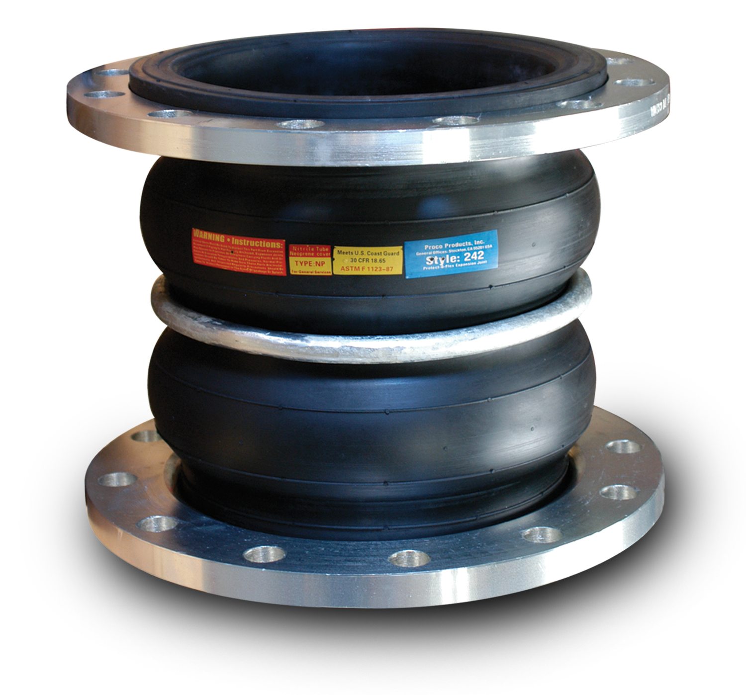
Proco Style 242
Proco Style 242 molded double-sphere rubber expansion joints are built to withstand even the most rigorous piping system configurations. They allow for axial compression or axial extension, and lateral deflection as well as angular movement. Their easy installation makes them the logical choice for even the toughest jobs.
Some of the notable features and benefits of the Proco Style 242 are:
- Absorption of Directional Movement
- Easy Installation with Rotating Metallic Flanges
- Wide Range of Flange Materials Available
- Absorption of Vibration, Noise and Shock
- Wide Range of Service and Lighter Weight
- Easy Material Identification
For more information about the features and benefits of the Proco Style 242, download our brochure.
For up-to-date pricing and availability information, contact Proco today.
Installation & Operation Manual Animation

| 242-A | 242-B | 242-C | PROCO Material Code | Cover Elastomer1 | Tube Elastomer2 | Maximum Operating Temp. °F (°C) | Branding Label Color |
|---|---|---|---|---|---|---|---|
| X | X | X | /BB3 | Chlorobutyl | Chlorobutyl | 250ºF (121ºC) | Black |
| X | X | X | /EE3,7 | EPDM | EPDM | 250ºF (121ºC) | Red |
| X | X | X | /NH | Neoprene | CSM | 212ºF (100ºC) | Green |
| X | X | X | /NN7 | Neoprene | Neoprene | 225ºF (107ºC) | Blue |
| X | X | X | /NP | Neoprene | Nitrile | 212ºF (100ºC) | Yellow |
Notes:
All Products are reinforced with Nylon Tire Cord, except 240-A and 240-C which are reinforced with Polyester.
1. All NN & NP elastomer designated joints meet the Coast Guard Requirements and conform to ASTM F 1123-87 and are marked accordingly.
2. Branding Label will be marked as “Food Grade”.
3. BB, EE, or EE-9 are good for 300°F blower service at 20 PSI or less.
4. 240-A & 240-C expansion joints have black EPDM tube, but are FDA compliant.
5. EE-9 joints are peroxide cured.
6. NP-9 joints have ABS certification.
7. Elastomers are in accordance with NSF/ANSI 372, File MH47689 Und. Lab. Classified.
8. All elastomers above are not intended for steam service.
9. For PTFE lined single sphere see www.www.procoproducts.com/ptfelined.html
10. For 240A & 240C Rubber Joints, Vacuum Support devices are available. Published movements will be reduced by approximately 50% for this option.
11. Series 240AV,D,E&M + 242A,B&C In Elastomers EPDM & Neoprene are all listed for lead content in accordance with NSF/ANSI 372
| Nominal Pipe Size I.D. | Neutral Length | PROCO Style Number1 | 242 Movement Capability: From Neutral Position (Non-Concurrent)2 | Pressure4 | Standard Flange Drilling Dimensions8 | Weight in lbs. | ||||||||||
| Axial Compression Inches | Axial Extension Inches | Lateral deflection Inches | Angular Deflection Degrees | Thrust Factor3 | Positive PSIG5 |
Vacuum6 |
Flange O.D. Inches | Bolt Circle Inches | Number of Holes |
Size of Holes |
Bolt Hole 7 Thread | Exp. Joint & Flanges | Control Unit Set (2 Rod) | |||
|
1 |
10.00 | 242-C | 2.000 | 1.188 | 1.750 | 45 | 4.43 | 225 | 26 | 4.25 | 3.13 | 4 | 0.625 | — | 5.2 | 3.6 |
|
1.25 |
7.00 |
242-A |
2.000 | 1.188 | 1.750 | 45 | 6.34 |
225 |
26 | 4.63 | 3.5 | 4 |
0.625 |
1/2-13 UNC |
5.3 |
3.5 |
|
1.5 |
6.00 |
242-B |
2.000 | 1.188 | 1.750 | 45 | 6.49 |
225 |
26 | 5.0 | 3.88 | 4 |
0.625 |
— |
6.1 |
4.6 |
|
2 |
6.00 |
242-B |
2.000 | 1.188 | 1.750 | 45 | 7.07 |
225 |
26 |
6.0 |
4.75 |
4 |
0.750 |
— |
9.0 |
6.6 |
|
2.5 |
6.00 |
242-B |
2.000 | 1.188 | 1.750 | 43 | 11.05 |
225 |
26 | 7.0 | 5.5 | 4 |
0.750 |
— |
12.9 |
7.6 |
|
3 |
7.00 |
242-A |
2.000 | 1.188 | 1.750 | 38 | 13.36 |
225 |
26 |
7.5 |
6.0 |
4 |
0.750 |
5/8-11 UNC |
14.3 |
8.6 |
|
4 |
9.00 |
242-A |
2.000 | 1.375 | 1.652 | 34 | 22.69 |
225 |
26 |
9.0 |
7.5 |
8 |
0.750 |
5/8-11 UNC |
20.3 |
8.0 |
|
5 |
9.00 |
242-A 242-C 242-C Q-242-HA |
2.000 | 1.375 | 1.562 | 29 |
30.02 |
225 225 225 300 |
26 |
10.0 |
8.5 |
8 |
0.875 |
— |
24.5 |
8.3 9.1 9.1 8.3 |
|
6 |
9.00 |
242-A |
2.000 | 1.375 | 1.562 | 25 | 41.28 |
225 |
26 |
11.0 |
9.5 |
8 |
0.875 |
3/4-10 UNC |
29.5 |
11.7 |
|
8 |
9.00 |
242-B |
2.375 | 1.375 | 1.375 | 19 | 63.62 |
225 |
26 |
13.5 |
11.75 |
8 |
0.875 |
— |
42.3 |
14.5 |
|
10 |
12.00 |
242-B |
2.375 | 1.375 | 1.375 | 15 | 103.87 |
225 |
26 |
16.0 |
14.25 |
12 |
1.000 |
— |
64.1 |
23.5 |
|
12 |
12.00 |
242-B |
2.375 | 1.375 | 1.375 | 13 | 137.89 |
225 |
26 |
19.0 |
17.00 |
12 |
1.000 |
— |
94.0 |
30.0 |
|
14 |
13.75 | 242-A | 1.750 | 1.118 | 1.118 | 9 | 182.65 | 150 | 26 | 21.0 | 18.75 | 12 | 1.125 | — | 142.0 | 32.0 |
|
16 |
12.00 |
242-C |
1.750 | 1.118 | 1.118 | 8 | 240.53 |
125 |
26 | 23.5 | 21.25 | 16 |
1.125 |
— |
154.0 |
28.8 |
|
18 |
12.00 |
242-C |
1.750 | 1.118 | 1.118 | 7 | 298.65 |
125 |
26 | 25.0 | 22.75 | 16 |
1.250 |
— |
168.0 |
35.1 |
|
20 |
12.00 |
242-C |
1.750 | 1.118 | 1.118 | 7 | 363.05 |
125 |
26 | 27.5 | 25.0 | 20 |
1.250 |
— |
202.0 |
35.0 |
|
24 |
12.00 |
242-C |
1.750 | 1.118 | 1.118 | 5 | 510.70 |
110 |
26 | 32.5 | 29.5 | 20 |
1.375 |
— |
220.0 |
47.0 |
|
30 |
12.00 | 242-C | 1.750 | 1.118 | 1.118 | 4 | 779.31 | 110 | 26 | 38.75 | 36.0 | 28 | 1.375 | — | 300.0 | 62.0 |
NOTES:
Standard Proco Style 242-A Expansion Joints shown in Bold Type are considered Standards and are inventoried in large quantities.
1. “HW” denotes Heavy Weight Construction. For sizes 2” I.D. thru 12” I.D., Proco will only offer these items with 300 lb. drilling and are denoted by Q-242-HW.
All Q-240-HW units will only be sold with control units.
2. Concurrent Movements – Concurrent movements are developed when two or more movements in a pipe system occur at the same time.
If multiple movements exceed single arch design there may be a need for an additional arch.
To perform calculation for concurrent movement when a pipe system design has more than one movement, please use the following formula:

Calculation must be equal to or less than 1 for expansion joint to operate within concurrent movement capability.
3. Calculation of Thrust (Thrust Factor). When expansion joints are installed in the pipeline, the static portion of
the thrust is calculated as a product of the area of the I.D. of the arch of the expansion joint times the maximum
pressure (design, test or surge) that will occur in the line. The result is a force expressed in pounds.
Take design, surge or test pressure X thrust factor to calculate end thrust.
4. Pressure rating is based on 170oF operating temperature. The pressure rating is reduced at higher temperatures.
5. Pressures shown at maximum “operating pressure”. Test pressure is 1.5 times “operating pressure”. Burst pressure is 4 times “operating pressure”. If factory hydro-test is required, an additional joint per size must be purchased and tested. Once hydro-tested this joint may not be sent to field for installation as the beaded end will have taken a (compressed) set and can not be reused.
6. Vacuum rating is based on neutral installed length, without external load. Products should not be installed in extension for vacuum applications. Flattening of the arch in extended mode will cause the arch to collapse.
7. Style 242A/NN (neoprene elastomer only) expansion joints 1.0” I.D. thru 12” I.D. are available with tapped (threaded) holes and must be specified at time of order.
8. In addition to standard 150 lb. drilled flanges, Proco can provide expansion joints listed above in 300 lb. drilling, BS-10 (British) drilling, Metric PN10 and PN16 drilling and JIS 10kg/cm drilling.
|
NOMINAL Pipe Size |
American 125/150# |
American 250/300# |
British Standard 10:1962 |
|||||||||||||
| Flange Thickness | Flange O.D. | Bolt Circle | No. of Holes | Drilled Hole Size | Threaded Hole Size | Flange Thickness | Flange O.D | Bolt Circle | No. of Holes | Hole Size | Flange Thickness | Flange O.D. | Bolt Circle | No. of Holes | Hole Size | |
|
1 |
0.55 |
4.25 |
3.13 |
4 |
0.62 |
1/2-13 UNC |
0.63 |
4.88 |
3.5 |
4 |
0.75 |
0.59 |
4.5 |
3.25 |
4 |
0.62 |
|
1.25 |
0.55 |
4.63 |
3.5 |
4 |
0.62 |
1/2-13 UNC |
0.63 |
5.25 |
3.88 |
4 |
0.75 |
0.59 |
4.75 |
3.44 |
4 |
0.62 |
|
1.5 |
0.55 |
5.0 |
3.88 |
4 |
0.62 |
1/2-13 UNC |
0.63 |
6.12 |
4.50 |
4 |
0.88 |
0.59 |
5.25 |
3.88 |
4 |
0.62 |
|
2 |
0.63 |
6.0 |
4.75 |
4 |
0.75 |
5/8-11 UNC |
0.71 |
6.50 |
5.00 |
8 |
0.75 |
0.63 |
6.0 |
4.5 |
4 |
0.75 |
|
2.5 |
0.71 |
7.0 |
5.5 |
4 |
0.75 |
5/8-11 UNC |
0.71 |
7.5 |
5.88 |
8 |
0.88 |
0.71 |
6.5 |
5.0 |
4 |
0.75 |
|
3 |
0.71 |
7.5 |
6.0 |
4 |
0.75 |
5/8-11 UNC |
0.79 |
8.25 |
6.62 |
8 |
0.88 |
0.71 |
7.25 |
5.75 |
4 |
0.75 |
|
3.5 |
0.71 |
8.5 |
7.0 |
8 |
0.75 |
5/8-11 UNC |
0.79 |
9.0 |
7.25 |
8 |
0.88 |
0.71 |
8.0 |
6.5 |
8 |
0.75 |
|
4 |
0.71 |
9.0 |
7.5 |
8 |
0.75 |
5/8-11 UNC |
0.79 |
10.0 |
7.88 |
8 |
0.88 |
0.71 |
8.5 |
7.0 |
8 |
0.75 |
|
5 |
0.79 |
10.0 |
8.5 |
8 |
0.88 |
3/4-10 UNC |
0.87 |
11.0 |
9.25 |
8 |
0.88 |
0.79 |
10.0 |
8.25 |
8 |
0.75 |
|
6 |
0.87 |
11.0 |
9.5 |
8 |
0.88 |
3/4-10 UNC |
0.87 |
12.5 |
10.62 |
12 |
0.88 |
0.87 |
11.0 |
9.25 |
8 |
0.88 |
|
8 |
0.87 |
13.5 |
11.75 |
8 |
0.88 |
3/4-10 UNC |
0.95 |
15.0 |
13.0 |
12 |
1.00 |
0.87 |
13.25 |
11.5 |
8 |
0.88 |
|
10 |
0.95 |
16.0 |
14.25 |
12 |
1.00 |
7/8-9 UNC |
1.02 |
17.5 |
15.25 |
16 |
1.13 |
0.95 |
16.0 |
14.0 |
12 |
0.88 |
|
12 |
0.95 |
19.0 |
17.0 |
12 |
1.00 |
7/8-9 UNC |
1.02 |
20.5 |
17.75 |
16 |
1.25 |
0.95 |
18.0 |
16.0 |
12 |
1.00 |
|
14 |
1.02 |
21.0 |
18.75 |
12 |
1.13 |
1-8 UNC |
1.10 |
23.0 |
20.25 |
20 |
1.25 |
1.02 |
20.75 |
18.5 |
12 |
1.00 |
|
16 |
1.10 |
23.5 |
21.25 |
16 |
1.13 |
1-8 UNC |
1.18 |
25.5 |
22.5 |
20 |
1.38 |
1.10 |
22.75 |
20.5 |
12 |
1.00 |
|
18 |
1.18 |
25.0 |
22.75 |
16 |
1.25 |
1 1/8-7 UNC |
1.18 |
28.0 |
24.75 |
24 |
1.38 |
1.18 |
25.25 |
23.0 |
16 |
1.00 |
|
20 |
1.18 |
27.5 |
25.0 |
20 |
1.25 |
1 1/8-7 UNC |
1.18 |
30.5 |
27.0 |
24 |
1.38 |
1.18 |
27.75 |
25.25 |
16 |
1.00 |
|
24 |
1.18 |
32.06 |
29.5 |
20 |
1.38 |
1 1/4-7 UNC |
1.18 |
36.0 |
32.0 |
24 |
1.62 |
1.18 |
32.5 |
29.75 |
16 |
1.25 |
|
30 |
1.26 |
38.75 |
36.0 |
28 |
1.38 |
1 1/4-7 UNC |
1.26 |
43.0 |
39.25 |
28 |
2.00 |
1.26 |
39.25 |
36.5 |
20 |
1.38 |
|
NOMINAL Pipe Size |
Metric Series |
Metric Series |
J.I.S. Standard B-2212 |
||||||||||||
| Flange Thickness | Flange O.D. | Bolt Circle | No. of Holes | Hole Size | Flange Thickness | Flange O.D. | Bolt Circle | No. of Holes | Hole Size | Flange Thickness | Flange O.D. | Bolt Circle | No. of Holes | Hole Size | |
|
1 |
0.63 |
4.53 |
3.35 |
4 |
0.55 |
0.63 |
4.53 |
3.35 |
4 |
0.55 |
0.59 |
4.92 |
3.54 |
4 |
0.75 |
|
1.25 |
0.63 |
5.51 |
3.94 |
4 |
0.71 |
0.63 |
5.51 |
3.94 |
4 |
0.71 |
0.59 |
5.31 |
3.94 |
4 |
0.75 |
|
1.5 |
0.63 |
5.91 |
4.33 |
4 |
0.71 |
0.63 |
5.91 |
4.33 |
4 |
0.71 |
0.59 |
5.51 |
4.13 |
4 |
0.75 |
|
2 |
0.71 |
6.50 |
4.92 |
4 |
0.71 |
0.71 |
6.50 |
4.92 |
4 |
0.71 |
0.63 |
6.10 |
4.72 |
4 |
0.75 |
|
2.5 |
0.71 |
7.28 |
5.71 |
4 |
0.71 |
0.71 |
7.28 |
5.71 |
4 |
0.71 |
0.71 |
6.89 |
5.51 |
4 |
0.75 |
|
3 |
0.79 |
7.87 |
6.3 |
8 |
0.71 |
0.79 |
7.87 |
6.30 |
8 |
0.71 |
0.71 |
7.28 |
5.91 |
8 |
0.75 |
|
3.5 |
— — |
— — |
— — |
— — |
— — |
— — |
— — |
— — |
— — |
— — |
0.71 |
7.68 |
6.30 |
8 |
0.75 |
|
4 |
0.79 |
8.66 |
7.09 |
8 |
0.71 |
0.79 |
8.66 |
7.09 |
8 |
0.71 |
0.71 |
8.27 |
6.89 |
8 |
0.75 |
|
5 |
0.87 |
9.84 |
8.27 |
8 |
0.71 |
0.87 |
9.84 |
8.27 |
8 |
0.71 |
0.79 |
9.84 |
8.27 |
8 |
0.91 |
|
6 |
0.87 |
11.22 |
9.45 |
8 |
0.87 |
0.87 |
11.22 |
9.45 |
8 |
0.87 |
0.87 |
11.02 |
9.45 |
8 |
0.91 |
|
8 |
0.87 |
13.39 |
11.61 |
8 |
0.87 |
0.87 |
13.39 |
11.61 |
12 |
0.87 |
0.87 |
12.99 |
11.42 |
12 |
0.91 |
|
10 |
1.02 |
15.55 |
13.78 |
12 |
0.87 |
1.02 |
15.94 |
13.98 |
12 |
1.02 |
0.95 |
15.75 |
13.98 |
12 |
0.98 |
|
12 |
1.02 |
17.52 |
15.75 |
12 |
0.87 |
1.02 |
18.11 |
16.14 |
12 |
1.02 |
0.95 |
17.52 |
15.75 |
16 |
0.98 |
|
14 |
1.10 |
19.88 |
18.11 |
16 |
0.87 |
1.10 |
20.47 |
18.50 |
16 |
1.02 |
1.02 |
19.29 |
17.52 |
16 |
0.98 |
|
16 |
1.18 |
22.24 |
20.28 |
16 |
1.02 |
1.18 |
22.83 |
20.67 |
16 |
1.18 |
1.10 |
22.05 |
20.08 |
16 |
1.06 |
|
18 |
1.18 |
24.21 |
22.24 |
20 |
1.02 |
1.18 |
25.20 |
23.03 |
20 |
1.18 |
1.18 |
24.41 |
22.24 |
20 |
1.06 |
|
20 |
1.18 |
26.38 |
24.41 |
20 |
1.02 |
1.18 |
28.15 |
25.59 |
20 |
1.30 |
1.18 |
26.57 |
24.41 |
20 |
1.06 |
|
24 |
1.18 |
30.71 |
28.54 |
20 |
1.18 |
1.18 |
33.07 |
30.71 |
20 |
1.42 |
1.18 |
31.30 |
28.74 |
24 |
1.30 |
|
30 |
1.26 |
37.99 |
35.43 |
24 |
1.30 |
1.26 |
38.19 |
35.43 |
24 |
1.42 |
1.26 |
38.19 |
35.07 |
24 |
1.30 |
| Table 5: | Standard Drilling for PROCO Rubber Expansion Joints | Thickness of Materials for PROCO Rubber Expansion Joints | Control Unite Plate Detail | |||||||
|
Nominal Pipe Size Expansion Joint I.D. |
Flange Dimensions2 | Material Thickness1 for Bolt Length Requirements | ||||||||
|
Flange O.D. |
Bolt Circle |
Number of Holes |
Size of Holes |
Bolt Hole Thread |
Nominal Flange/ Beaded End Thickness |
Adjacent Mating 3 Flange Thickness |
Max. Control4 |
Control Rod6 |
Maximum7Rod Diameter |
|
|
1 |
4.25 |
3.13 |
4 |
0.625 |
1/2-13 UNC |
1.25 |
Customer to specify mating flange thickness |
0.375 |
8.375 |
0.625 |
|
1.25 |
4.63 |
3.5 |
4 |
0.625 |
1/2-13 UNC |
1.25 |
0.375 |
8.750 |
0.625 |
|
|
1.5 |
5.00 |
3.88 |
4 |
0.625 |
1/2-13 UNC |
1.25 |
0.375 |
9.125 |
0.625 |
|
|
2 |
6.00 |
4.75 |
4 |
0.750 |
5/8-11 UNC |
1.25 |
0.375 |
10.125 |
0.625 |
|
|
2.5 |
7.00 |
5.50 |
4 |
0.750 |
5/8-11 UNC |
1.25 |
0.375 |
11.125 |
0.625 |
|
|
3 |
7.50 |
6.00 |
4 |
0.750 |
5/8-11 UNC |
1.25 |
0.375 |
11.625 |
0.625 |
|
|
3.5 |
8.5 |
7.0 |
8 |
0.750 |
5/8-11 UNC |
1.25 |
0.375 |
12.625 |
0.625 |
|
|
4 |
9.00 |
7.50 |
8 |
0.750 |
5/8-11 UNC |
1.25 |
0.375 |
13.125 |
0.625 |
|
|
5 |
10.00 |
8.50 |
8 |
0.875 |
3/4-10 UNC |
1.50 |
0.500 |
14.125 |
0.625 |
|
|
6 |
11.00 |
9.50 |
8 |
0.875 |
3/4-10 UNC |
1.50 |
0.500 |
15.125 |
0.625 |
|
|
8 |
13.50 |
11.75 |
8 |
0.875 |
3/4-10 UNC |
1.50 |
0.750 |
19.125 |
1.000 |
|
|
10 |
16.00 |
14.25 |
12 |
1.000 |
7/8-9 UNC |
1.50 |
0.750 |
21.625 |
1.000 |
|
|
12 |
19.00 |
17.00 |
12 |
1.000 |
7/8-9 UNC |
1.50 |
0.750 |
24.625 |
1.000 |
|
|
14 |
21.00 |
18.75 |
12 |
1.125 |
— |
1.75 |
0.750 |
26.625 |
1.000 |
|
|
16 |
23.50 |
21.25 |
16 |
1.125 |
— |
1.75 |
0.750 |
30.125 |
1.250 |
|
|
18 |
25.00 |
22.75 |
16 |
1.250 |
— |
2.00 |
0.750 |
31.625 |
1.250 |
|
|
20 |
27.50 |
25.00 |
20 |
1.250 |
— |
2.00 |
0.750 |
34.125 |
1.250 |
|
|
24 |
32.00 |
29.50 |
20 |
1.375 |
— |
2.00 |
1.000 |
38.625 |
1.250 |
|
|
30 |
38.75 |
36.00 |
28 |
1.375 |
— |
2.00 |
1.250 |
46.375 |
1.500 |
|
Metric Conversion Formula: Nominal I.D.: in. x 25 = mm; Dimensions/Thickness’: in. x 25.4 = mm.
Notes:
1. Limit/Control Rod length is determined by neutral length of rubber expansion joint, rated extension, control rod plate thickness, mating flange thickness and number of nuts. Consult PROCO for rod lengths.
2. Flange Dimensions shown are in accordance with ANSI B16.1 and ANSI B16.5 Class 125/150, AWWA C-207-07, Tbl 2 and 3 – Class D, Table 4 – Class E. Hole size shown is 1/8” larger than AWWA Standard.
3. Adjacent mating flange thickness is required to determine overall rod length and compression sleeve length (if required).
4. Plate thickness is based on a maximum width PROCO would use to design a Limit/Control Rod plate.
5. Flat Washers required at ring splits and are supplied by others.
6. Control rod plate O.D. installed dimension is based on a maximum O.D. Proco would supply.
7. Control rod diameter is based on a maximum diameter Proco would use to design a control rod.
A control rod unit consists of limit rods, tie rods, or compression sleeves, and a control unit assembly is a system of two or more control rod units placed across an expansion joint from flange to flange. Their purpose is to minimize possible damage caused by possible excessive motion of a pipeline. Control unit assemblies can be set at the maximum allowable expansion and / or contraction of the rubber expansion joint.
When used properly, control unit assemblies serve as additional safety enhancements, and can minimize possible damage due to adjacent equipment.
Rubber expansion joints should be installed between two fixed anchor points in a piping system. When proper anchoring can’t be provided, control units are required. When an un-anchored piping system is encountered, nuts should be tightened securely against the rod plate, to prevent over-extension due to pressure thrust caused by the expansion joint.
Listed below are three control unit configurations supplied by Proco, that are commonly used with rubber expansion joints in piping systems.
- Figure 1: Limit Rod. A limit rod control unit configuration will allow an expansion joint to lengthen to a predetermined extension setting. Spherical washers can also be furnished, upon request, to prevent any “nut to plate” binding during offset.
- Figure 2: Limit / Control Rod. This type of configuration is used to allow specified pipe expansion (expansion joint axial compression) and pipe contraction (expansion joint axial extension) movements. Spherical washers can also be furnished, upon request, to prevent any “nut to plate” binding during offset.
- Figure 3: Compression Sleeve. A compression sleeve configuration is used to allow for specified pipe expansion (expansion joint axial compression) and pipe contraction (expansion joint extension) movements. Proco will supply each compression sleeve equipped to prevent any axial movement, unless otherwise specified at the time of purchase. Spherical washers can also be furnished, upon request, to prevent any “nut to plate” binding during offset.
For more information on Proco control unit specifications, download our Style 242 Brochure.
For up-to-date pricing and availability information, contact PROCO today.
In order to properly and successfully install a Proco Style 242 non-metallic expansion joints with beaded end flanges, specific conditions must be met. It’s also important to ensure the process is implemented using the guidelines set forth in our brochure. Contact Proco for additional advice if the system requirements exceed those of the expansion joint selected.
For detailed information on service conditions, proper alignment, anchoring, and storage techniques, download the Proco Style 242 Brochure.